Update 17.4.22: Equalised the audio levels on the videos at the end of this page + added a video of VK3MO on 20m.
Update 9.11.21: V1.20 software (back-port of the V2 receiver code-base) is available via ftp or email. This is now the preferred software; even though it is indistinguishable from the previous version it is more efficient internally. Functionally it is the same as V1.06
Update 1.6.21: I have back-ported the V2 receiver code-base (re-organised code with 256 colour / 8bpp graphic mode) to my V1.2 hardware. This is now undergoing beta-test. This uses the original Discovery board port-mapping and therefore does not have UARTs and therefore CAT. A version with the new Discovery board port-mapping and the old V1.2 hardware will be next. Further kitting of V2 receiver is underway, though still with component shortages!
Update 14.5.21: No changes to V1.2 design. V2 receiver is finished. Availability of V2 kits is still delayed pending component availability.
Update 6.2.21: V1.06 of the software released for V1.2 receiver; this adds a wide Rx bandwidth on AM mode (AM 6dB widths are now 6.4kHz, 8.6kHz and 12.8kHz). New page added for V2 receiver.
Older updatesHome-Brew STM32 HF SDR Receiver by Tim Howe, G0ETP
(For the new V2 receiver click here)

Key Features
There are a lot of home brew SDR-related projects on the internet at the moment. I believe the key features of this project are:
- Small but conventional radio form-factor with tuning knob AND NO PC
- A clear graphical display with S meter and real-time band-scope/waterfall (very high update-rate makes the radio a pleasure to use)
- Smooth DDS tuning with steps down to 10Hz (optical shaft encoder)
- All mode operation with excellent SSB and CW filtering (NOT double-sideband) and a decent AGC
- There are no analogue components to adjust or align, so if built correctly the radio 'will just work'
- Based on a very low cost, commercial CPU / Display board
- Cost of major parts is about £80 (UK) assuming stuff like a case, knobs, speaker, audio amp etc can be found 'in the junk box'.
Please bear in mind that this project will require soldering of 0603-size SMD components and a couple of fine-pitched ICs (see photo of radio PCB below).
Please contact me at moc.dlrowltn@321ylbmit (reversed) or via qrz.com for information on getting a partial kit for the radio board. The parts kit comprises the PCB, most of the passives and many of the ICs (does NOT include the 1.8V regulator, the op-amps or the DDS). The price is currently £35 to the UK, £37 to the EU and £38 to the rest of the world. The PCB is now a proper 2-layer manufactured board with plated through VIAs, solder mask and silk screen. See here. Additional build documentation will be sent out by email and this includes the buying list for the remaining parts.
I am getting lots of email, so please check the FAQ before posting questions, thanks.
There is a failrly detailed walk-through of the radio and its features on YouTube here. There is also an older and less structured video here and various videos at the bottom of this page. (Please allow for the low bandwidth of my internet link!) Also see www.qrz.com/db/G0ETP
Pre-Selector Filter Boards
A design for a multi-band pre-selector filter for this radio is currently underway as a separate project and PCB. There is also growing support in the software for a number of 3rd-party preselector filter boards. For more details see here
Reviews and Other Links
This radio has been spotted on qrznow.com and on soldersmoke.blogspot.co.uk. The guys at Soldersmoke had some kind words to say in their audio podcast #194 which you can hear here:
Other Build Examples
Ross Mackay has completed his build and has kindly provided pictures and details here.
Oleg Gaushkin UR5UEG has his radio built and running. There is a short video on YouTube here.
Serge RV3APM has his radio built and running. There are some videos on YouTube posted under 'DXRadio 2014'.
Gyula Molnar (HA3HZ) built his receiver a couple of years ago but it has just undergone a re-build, resulting in a compact form very similar to my portable version. It looks very tidy indeed. See his web page here. There is a short video on YouTube here. (Note that he is aware of the audio amplifier distortion and this is now resolved.)
I have built a portable / travel version of this receiver. See here.
G0ETP HF SDR Receiver - General Overview
This is a completely scratch-built HF Rx made for my entertainment and enjoyment, with virtually nothing copied from other designs. At its centre is an ST-Micro STM32F429I Discovery board, which has an ARM CoretexM4 processor with hardware floating point, various peripherals and a 320x240 pixel LCD, all for ~£23 UK. This is paired with an own-design receiver PCB. The radio is a direct-conversion (zero-IF) design comprising a 26MHz TCXO, an ADI995x DDS Local Oscillator, RF preamp, QSD mixer, IQ filters and a 24bit stereo ADC. Tuning is achieved purely by moving the DDS LO whilst all DSP functions remain (nominally) at the same baseband frequency. I am currently running the IQ ADC at 25k samples per second which gives a baseband width (and band-scope span) of 25kHz.
The main tuning control is a 256-step per revolution optical Bourns shaft encoder and is very smooth. Tuning steps can be selected from 10Hz, 100Hz, 500Hz, 1kHz and 10kHz, plus there is a 100kHz mode for moving between bands. The shaft encoder step rate is geared according to the step size and this prevents the tuning from being unusably sensitive at the coarser step sizes. Now that most people have accurate references in their Tx, the need for 10Hz tuning is almost outdated and I find that 100Hz steps are perfect for CW and 500Hz for SSB. Most stations just 'snap' into perfect tune and I almost never have to resort to fine-tuning an SSB station. In fact, I now find conventional radios with 10Hz steps quite tiresome to tune as you 'faff' to get the Hz readout to 0!
There are 4 buttons for common functions: VFO A/B + VFO copy, mode selection, display mode selection and tuning step selection. All less-common functions are located on a menu that is driven by a low cost push/rotate shaft encoder. This menu encoder is most frequently left in the 'RF gain' mode, as this is most useful in managing background noise and reducing listener fatigue. Finally, there is a good old-fashioned 'pot' for volume.
Software Overview
The software has been generated almost entirely under Linux using the Eclipse (Kepler) IDE with plug-in support for the ARM EABI GCC cross compiler and the OpenOCD debugger. Rebuilding the code and downloading via a USB cable is a breeze.
As of version 1.02, the software features are as follows:
SSB, CW, AM and FM demods with a well-developed AGC (including impulse-noise recovery), 'AGC Gain Cap' control for effective background noise management, accurate RSSI reporting (both dBm display and analogue S-meter), selectable tuning steps, IF normal, wide and narrow bandwidths, IF shift, 2 notch filters (tunable in 1Hz steps), selectable DDS reference multiplier, TCXO freq calibration plus various other settings. The battery backed up RAM in the ST Micro is used so that all parameters that need to be non-volatile are retained when the power is off.
The user interface updates at 60 frames per second. The 'DSP display area' has a real-time FFT band-scope and a waterfall display, both of which update at 30 frames per second. In addition to providing text decode of CW signals, the software now includes decoding of RTTY (45.45 BAUD 170Hz shift) and PSK (31.25, 62.5 and 125 BAUD) signals and features a graphical tuning indicator.
The waterfall display is somewhat different to that seen on PC-based SDRs as in this design, ALL tuning is performed by moving the RF LO; this means that lines on the waterfall display will smear as the radio is tuned. In order to be able to home-in quickly on a signal in the waterfall history, I have made the waterfall scroll sideways as the radio is tuned. Its a pretty neat solution but was more difficult than expected, requiring careful matching of the Rx path group delay and subsequent processing delays so that the scrolled history and new signals remain aligned!
Floating-point IIR filters have been used in the baseband processing as they offer exceptional performance for very little CPU load, plus we don't care much about the phase response for audio applications. The channel filters are either 6th order or 8th order elliptic designs (depending on mode) and exhibit fantastic adjacent channel selectivity whilst not sounding too sharp. Passband ripple for SSB is 2dB and stop band performance is -80dB, which is more than adequate for all but the most extreme adjacent-channel situations. I ended up using type 1 Chebychev filters on CW as these have 0dB passband ripple and (I think) are more forgiving of small tuning errors, plus they sound nicer than the elliptic ones. Stop band performance is again -80dB. Given that the AGC does not respond to signals outside the main passband, the close-in adjacent channel performance on busy bands is remarkable for a radio of such low cost and simple design.
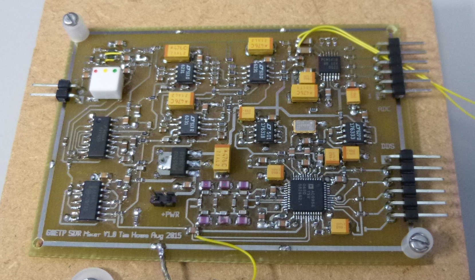
Radio PCB:
This board was created using GEDA under Linux and hand-routed entirely on a single layer over a solid ground-plane. It was hand-etched, drilled and assembled by me, thankfully with access to a decent microscope (soldering the AD9954 DDS was about at the limit of my eyes and my soldering!!). V1.0 of the radio board is up and working with only 1 mistake on the LNA, which I don't think is bad considering that none of the circuit was breadboarded in advance! The prototype PCB can be seen here. This is still in use in my receiver.
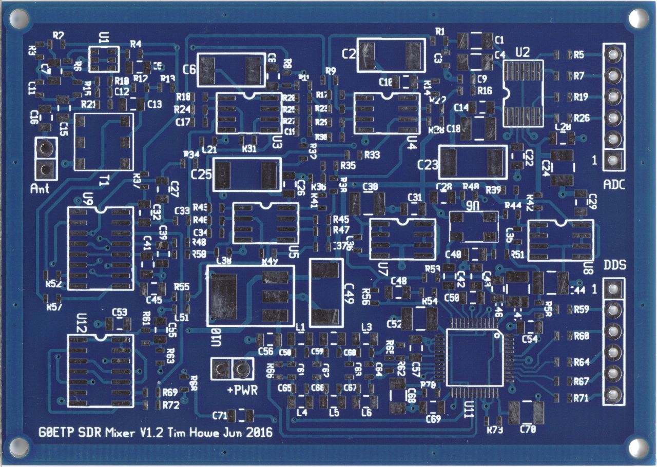
The new fabricated PCB looks like this and is great, apart from a little silk-screen text clipping. A fully assembled blue board is shown below. Check this picture if you have any questions about component orientation when you are building (particularly the orientation of the electrolytic capacitors and ICs). You can't see it very well in this picture but the TCXO is upside down.

The functional block diagram is as follows:

The VFO is generated by an Analog Devices AD9954 DDS (although the cheaper 9952 will do) running at an internal rate of 390MHz (15 x 26MHz). Its balanced output passes through a balanced LC low pass filter and back into the chip's internal comparator for squaring. (Note that an analogue LPF is an essential part of the DDS process, as it performs interpolation and reduces jitter.) The squared clock passes into a synchronous divide-by-4 counter (160MHz 74AC74) that generates I and Q clocks to commutate the Quadrature Sampling Detector (FST3253). I have used ultra low-noise LT6231 op-amps for the I and Q differential amplifiers and low-pass filters. Finally the I and Q signals pass into a Burr Brown (Now Ti) PCM1808 24bit ADC. This is not the world's best 24bit ADC by modern standards but I had a few and it is proving more than adequate. The ADC clock is provided by the ARM board.
The RF input stage may seem rather low-tech: It is an LT6230-10 single 1450MHz-GBP op-amp configured to give a broadband 50 ohm input impedance, a little gain and buffering to drive the QSD mixer via a balun transformer. Mixers are notoriously nasty to drive as their input impedance changes as they commutate, so buffering is necessary, plus it helps to reduce the amount of LO that leaks out of the antenna port. Even though the input stage contains resistors (sacrilege in low-noise RF circuits!), the overall noise performance of the receiver is adequate for use on HF (see 'Other Performance Aspects' below). The key advantages of using an op-amp here is that the design is not sensitive to parameter variation the way a transistor amp is and it provides tremendous dynamic range (good IP3), especially given the single 5V supply rail.
Radio Construction:
Notes on assembling and testing the radio PCB are shipped out with the kit, along with the circuit schematics and additional documentation.
My radio has been built into the case of a dead Halcyon Electronics off-air standard! This is a nice sturdy steel case. However, a major issue was the fact that it is not tall enough to accommodate the STM32F429I Discovery board: I had to lift the LCD display, remove the flexi cable, mount the display on the front panel and run 48 wires to the processor PCB! I would not recommend this to anyone unless they have as much patience as me; the best option is simply to pick a taller case.
If you do mount the Discovery board directly behind the front panel, I would still recommend prizing the LCD off its foam pads and re-sticking it so that it stands more proud of the board; 10mm would be nice, as this would allow the 4 mode buttons to be squeezed in between the LCD and the main tuning control. Since I do not use the touch screen capability (the screen is too small) I have made a perspex (plexiglass) window that sits in the metal panel aperture. This serves as part of the LCD retaining mechanism and also provides protection.
As the pictures below will show, the radio is not pretty inside. I have fixed a sheet of PCB material inside the case as a 'base plate', onto which I have soldered mounting screws (these can easily be moved without leaving drill-holes everywhere). I may tidy the inter-board wiring in the future but it doesn't show when the lid is on and everything seems to work fine. (The 'casual' internal wiring may prove to be responsible for some of the unwanted Rx spurs but I'll investigate those at a later point.)
Internal Layout showing the ARM board, the radio board and the audio amplifier board, the front panel controls and the LCD mount. As of May 2018 there is now an HA8LFK filter board and a MAR-6SM+ LNA in place of the op-amp LNA:

LCD hand-wiring:


And now we can't see all the nasty wiring it looks EPIC (and yes those holes did take me ages to drill...):

The Radio In Operation
Tuning and Waterfall
With the waterfall scrolling sideways as you tune, together with the 500Hz step size, SSB tuning is a cinch! The band-scope may only span +-12.5kHz but this provides great 'situational awareness' without losing too much display detail, as would happen if it spanned the whole band. The waterfall is particularly useful in CW mode as the passband is so narrow you can easily be unaware of stations nearby. (I actually feel blind going back to a traditional radio with no band-scope!)
S-Meter
Not only does the S-meter look great, it is accurate to ~1dB. I have elected to leave the S-meter reading alone when the max AGC gain (RF gain) is backed off; this way you can see what's really happening on the channel, rather than having the S-meter rendered useless, as is the case on most radios. (On such radios, the S meter simply shows that the AGC control line has been pushed up by the RF gain control.)
Audio Quality
Because the filters are effectively 16th-order band-pass Elliptic, the skirts are very steep. With the BFO placed at approximately the -20dB point, the bass response in SSB mode is great. In headphones, some stations sound terriffic; K1KW is someone who obviously takes a lot of care over his transmitted audio (he even uses PA predistortion!) - I have never heard such clear, intermodulation-free SSB audio. Apart from the expected 'narrow-bandness' of the CW filter, CW is very easy on the ears and my AGC is completely free from overshoot. Backing off the max AGC gain (equivalent to RF gain) makes for very comfortable listening.
Other Performance Aspects
The analogue gain of the receiver board has been set as a compromise between sensitivity and large signal handling: The noise figure is 29dB (with V1.2b BOM values) which may seem high but is acceptable, as on HF the natural and man-made noise floor is usually 30-50dB above thermal noise. The ADC caves in at -23dBm input (S9+50dB), so it is unlikely that you'll need an external attenuator unless there is a strong station nearby. (Note that by >24MHz the HF noise floor will have dropped-off and a lower NF would be beneficial: Feel free to connect an external LNA.)
IQ mixer balance and opposite-sideband rejection is at least 45dB without any digital compensation, which is better than expected. As you head above 21MHz the mixer balance begins to worsen and some common-mode signal breakthrough becomes apparent. It is possible to reduce this common-mode breakthrough by fitting a high-pass filter on the antenna socket. (I made a 3rd-order-T HPF at approx 3MHz out of 2 back-to-back BNC connectors. Component values are 1nF series, 1uH to ground and another 1nF in series.)
There are a number of unwanted 'spurs' on various bands but this is common with simple designs such as this. These are mostly recognisable by the fact that they dont stay still on the waterfall when the radio is tuned. The majority of these appear to be coming from signals like the ADC clock (and harmonics of) and possibly other clocks on the ARM board. As yet I have not put any effort into chasing these down and reducing them. Those spurs that are caused by DDS sidebands can be dodged by moving the DDS reference multiplier in the menu. The STLINK USB programming port on the Discovery board is responsible for some of the identified interferers - you might like to look into ways to disable this when it is not needed for programming.
I will add some mp3 files in due course.
Video clips
ZF2CA during the 2016 BERU contest
20m band CW mode (250Hz filter). Note that 'basic' cameras do not seem to like filming LCD displays and these clips do not do justice to the clatrity of the actual display. Also, the beat between the screen and camera's frame rate make the CW-scroll at the bottom of the screen look juddery when in fact it is not.
Video 1: Showing CW decode display
Video 2: Showing waterfall display followed by CW decode display
Video 3 (different camera): Showing CW decode display
Video 4: Showing CW decode, followed by FFT then waterfall displays
Clips showing SSB mode
Video 5: YB0IBM on 14.228 5 May 2016 18.30 UTC. No grief from the adjacent channels.
Video 6: Tuning around 20m, 5 May 2016 18.40 UTC. JH1AJT under a pileup on 14.213.
Video 7: Example of RTTY (45baud / 170Hz shift) decoding.
Video 8: Very first PSK31 decode on 20m 18 June 2019 (Mk 1 demodulator).
Video 9: Very first PSK63 decode on 40m 18 June 2019 (Mk 1 demodulator).
Video 10: First decent reception of DRM; RRI from 'SNR Tiganesti E2'. COFDM audio fed into Dream software running on Linux platform. 6090kHz, 9.04.2020.
Video 11: VK3MO (monster station near Melbourne) booming in on 20m long path, 09:50 UTC 17.04.2022.
This is good for VK given my mediocre antenna and high noise floor. Remember this S meter reads exactly, so he is peaking S9.
Last updated: 12.1.2023