Update 11.7.22: The portable Mk2 build page is about done: The V2 Portable Build
Update 28.6.22: Portable build based on the Mk2 design is now about done (besides making a plastic mask to go inside the box lid to hide the Disco board). I have identified the cause of the buzz that can be heard when the tuning knob is turned quickly - this comes from the TUN_CH1 line and is some appalling PCB routing on my part. This can be solved with a simple cut and strap on the underside of the radio PCB - see the portable build page (work in progress) for details.
Update 17.6.22: Now that pressures at work have dropped from insane to high, I have begun a last push to get my Mk2 receiver assembled into the Hammond RP1175C box, something that I started more than a year ago!! I will shortly be adding a sub page for this with some pictures and assembly notes.
Older updatesMk 2 Home-Brew HF SDR Receiver by Tim Howe, G0ETP
A complete, multi-mode HF + 6m SDR receiver as an easy, plug-on 'shield' for the STM32F429I Discovery Board
Key Features compared to the V1.2 Receiver
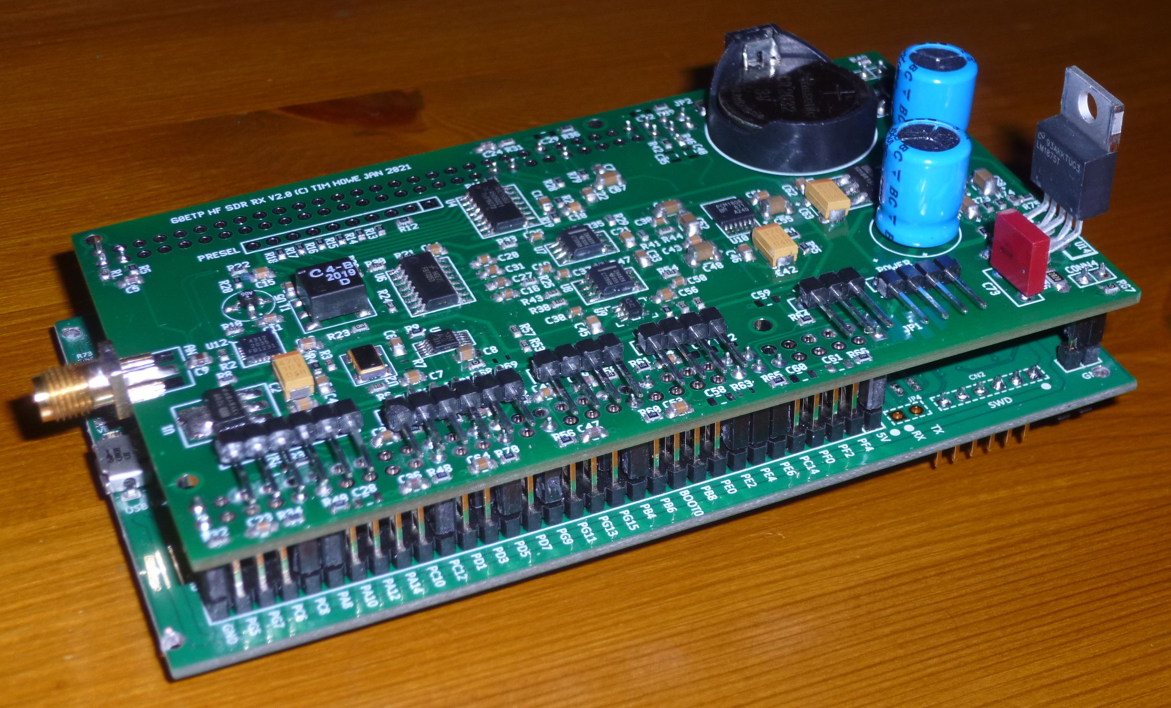
This project still requires soldering of 0603-size SMD components and a couple of fine-pitched ICs. It now includes a QFN-20 RF IC which is not too difficult with the correct soldering technique.
Notes/advice on QFN soldering.Kits comprising the majority of the parts required to build the radio PCB are available. However, given the degree to which global component shortages is ongoing, I suggest you begin by emailing me for a BOM listing (moc.dlrowltn@321ylbmit (reversed) or via qrz.com) so that you can make sure you can get hold of (or already have) the non-kitted parts needed to complete the receiver.
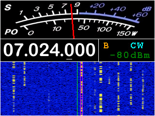
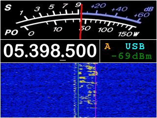
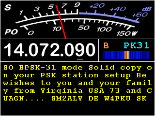
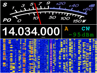
Screen-Dumps Illustrating the User Interface
Additional Pictures of the Assembly
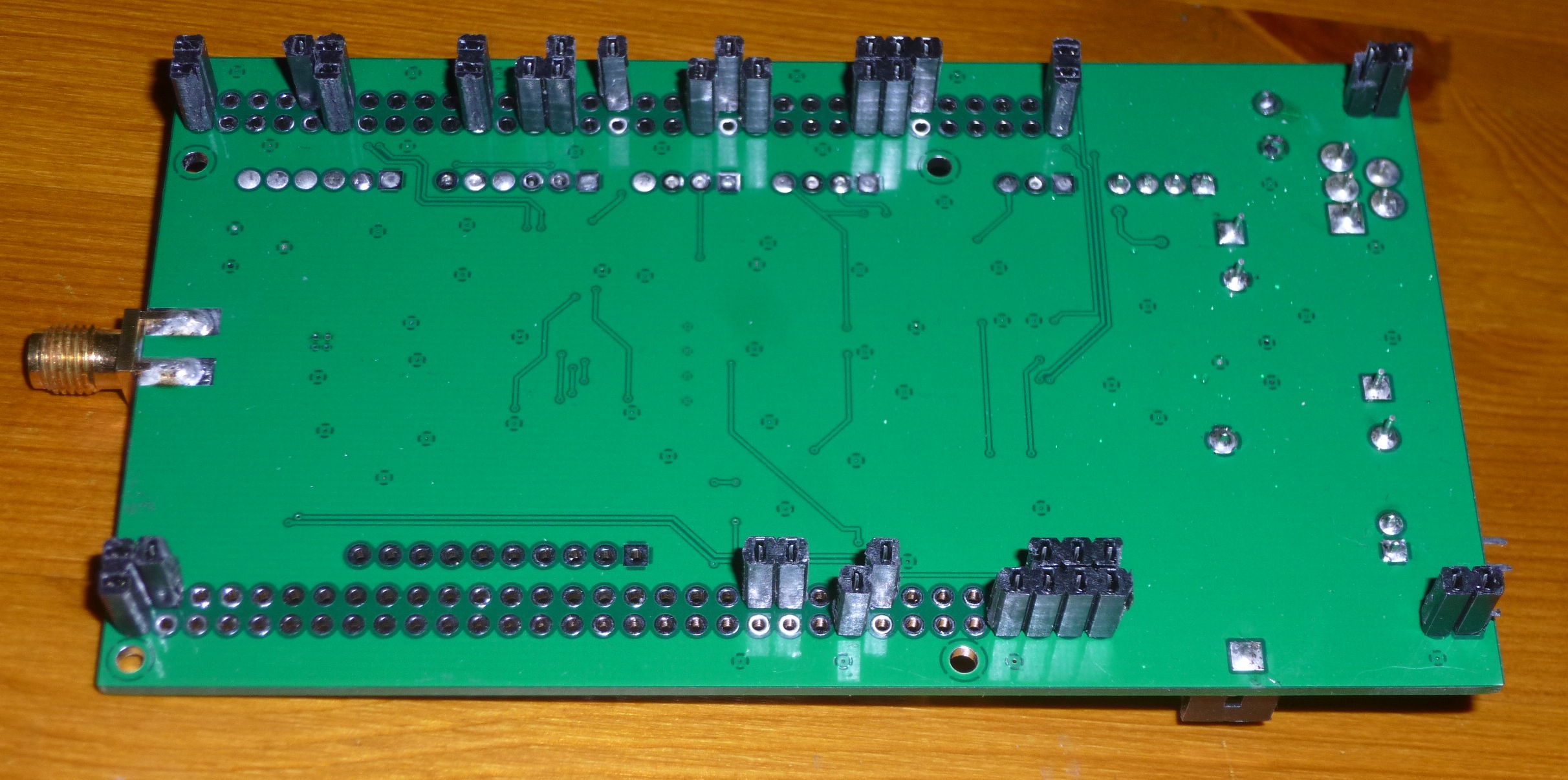
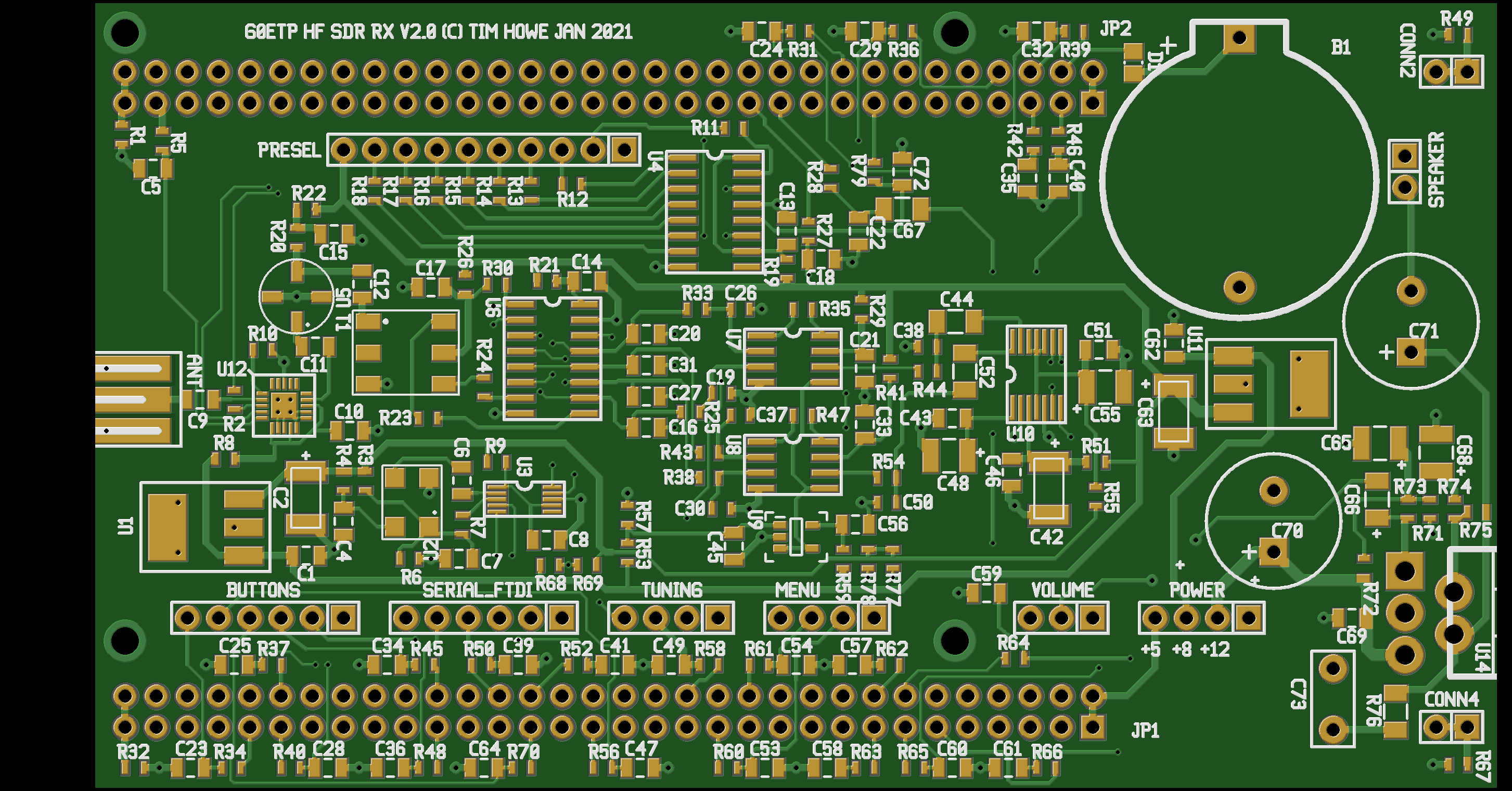
V2 Receiver PCB - Component Side View: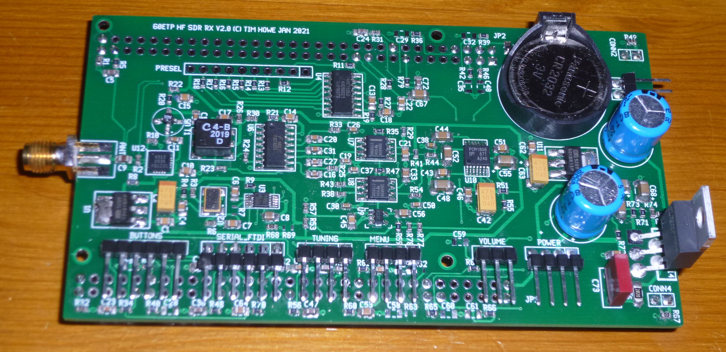 V2 Receiver PCB - Underside View showing connectors that mate with the STM32 board:
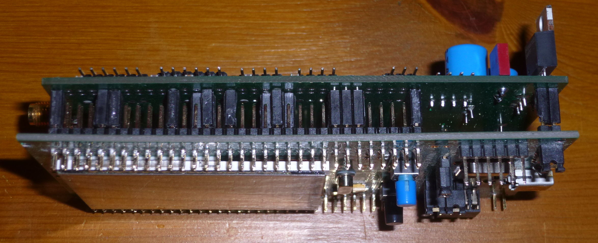
 V2 Receiver board attached to the STM32 Discovery:
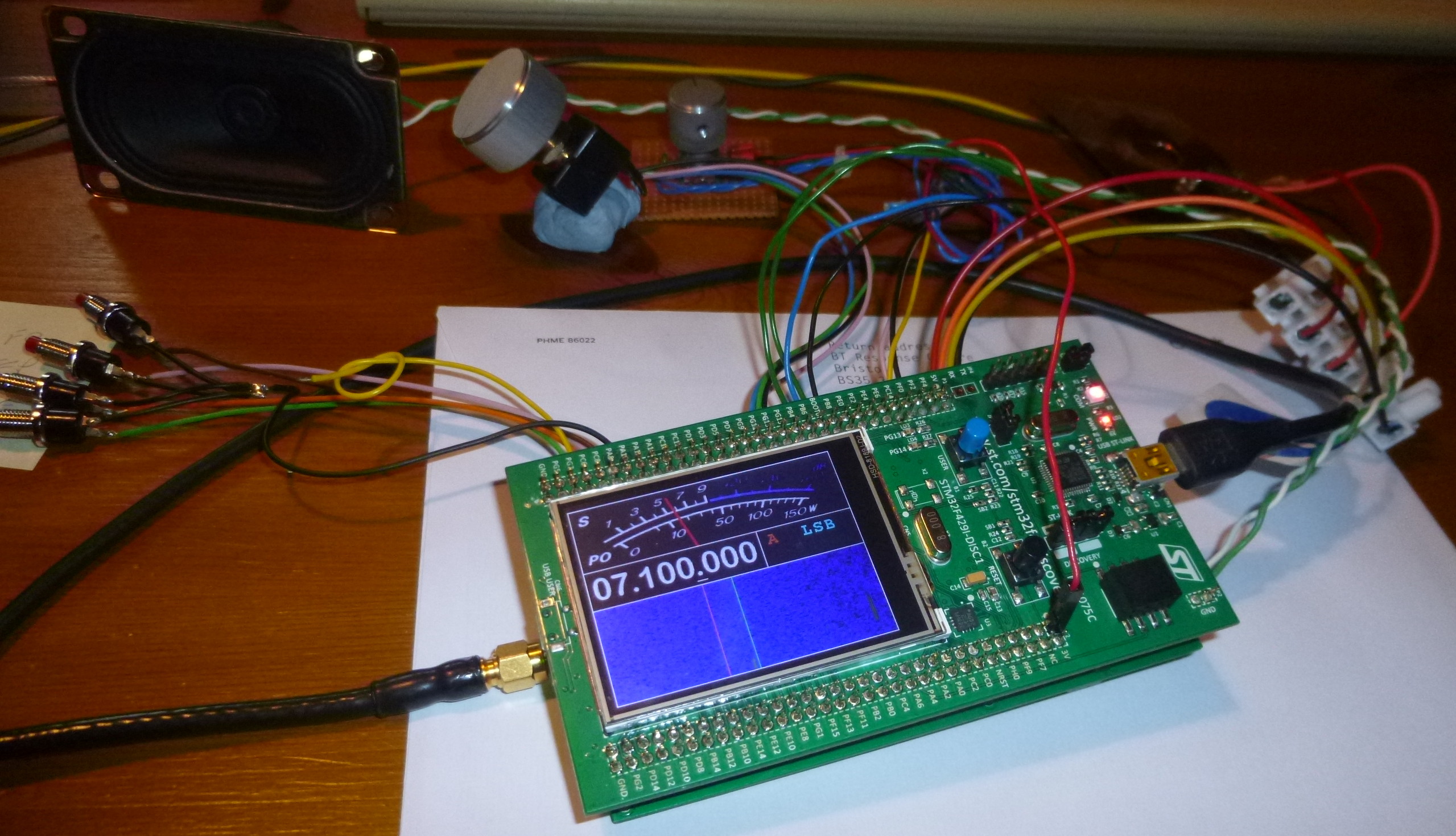
 Early picture of V2 Receiver in operation:
The PCB can be seen here
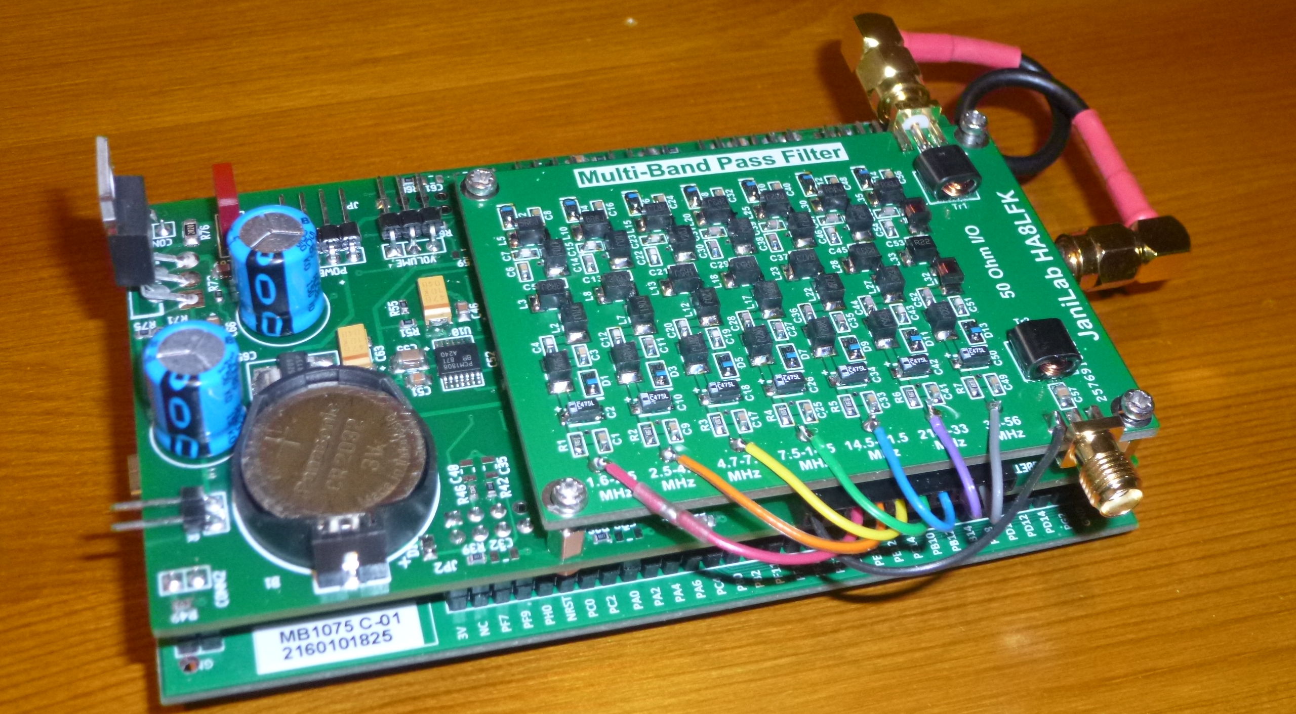
Now with the 7-band preselector filter fitted:
Video clips
Video 1: Sample of 80m SSB, 26.2.2021
Video 2: Tuning around 20m SSB + using the notch filters, 7.3.2021
Last updated: 12.1.2023