Portable Build of G0ETP's HF SDR Receiver (April 2018)
Update 17.2.21: The Mk2 receiver design is massively more suited to building a portable receiver than the Mk1.2. Now this design is up and running, I would urge you to take this route for a portable. The only real limitation is that it will not cover frequencies below 1.8MHz.
Update 22.1.21: The prototype Mk2 receiver design has just gone to PCB fab - way too many vias to contemplate hand etching this one! This board is effectively a plug-on shield to the STM32F429I Discovery board and is highly suited to making a compact portable receiver. Watch this space for progress after the initial board bring-up.
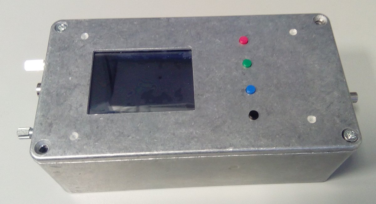
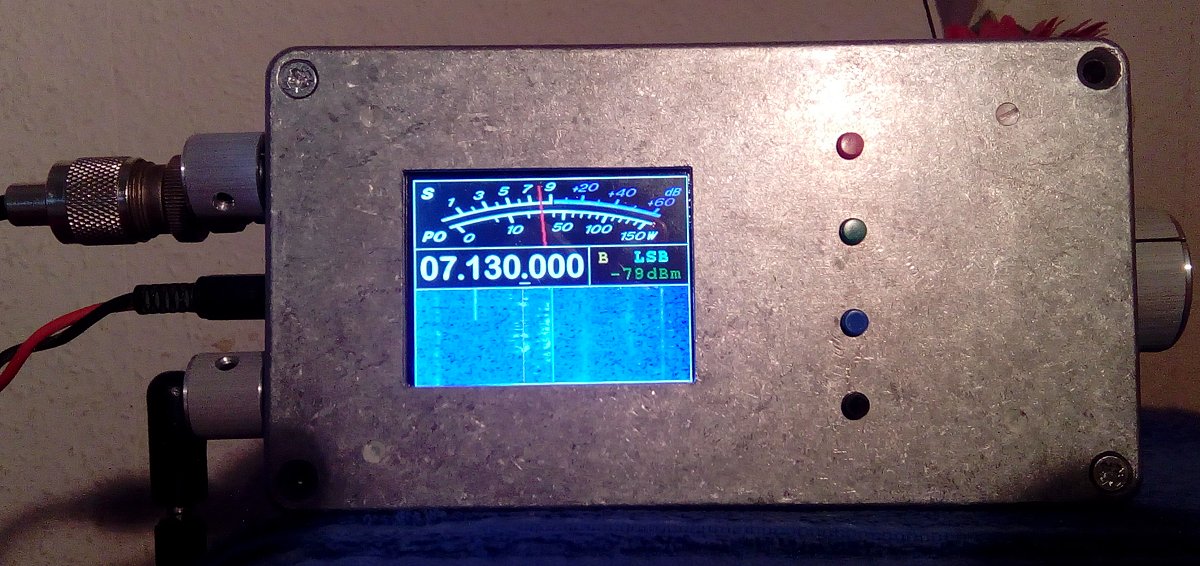
I stumbled upon a Hammond 1590P1 diecast box in the bin at work the other week and this fuelled me to go ahead and build my second Rx. This box measures 153 x 82 x 50mm, so it was going to be something of a challenge to fit everything in.
First off, the box already had holes drilled in it so true to my father's recycling talents, I covered the outside of these with Sellotape and filled them with polyester resin. After that, planning commenced.
Front Panel and Control Layout
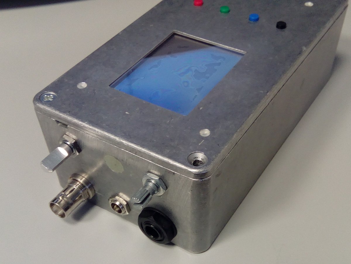
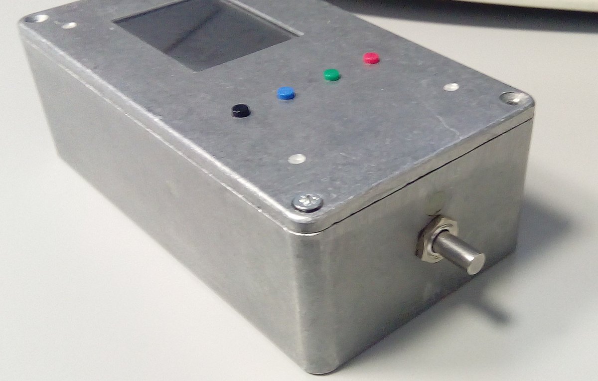
I have believed for some time that it must be possible to make use of the wasted space to the right of the LCD display (caused by the design of the ST DISCO board) by squeezing the 4 control buttons in between the DISCO board and the front panel. Doing this would allow the front panel to have both the LCD display window and the 4 function buttons. I used SMD tactile switches (Mouser part # TBC). Given the size of the DISCO board in relation to this box, there is simply no more room on the front panel for anything else. After some deliberation I decided to put the tuning encoder on the right-hand end of the box and everything else on the left-hand end. The speaker holes will be on the back.
DISCO Board Preparation
In order to mount the control buttons between the DISCO board and the front panel it is necessary to clear space on the top side of the board as follows: The USER and RESET buttons are removed, the SWD header (CN2) is removed, the IDD (JP3) and STLINK jumpers (CN4) are moved to the underside, JP1 and JP2 are removed, CN3 is removed and the top-side of all the pins on P1 and P2 are clipped:
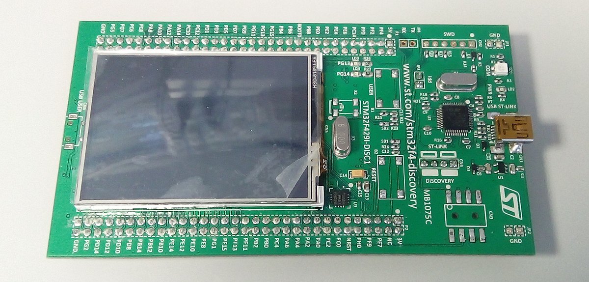
Having done this it is then time to drill a number of holes directly through the DISCO board. I have checked where these holes go against the Gerber files supplied by ST, so provided that nylon screws are used, all should be well!
4 M2 holes are drilled for mounting the DISCO board to the front panel. A small piece of 0.1" Vero Board can be used as a drill guide by placing it over some of the header pins on the DISCO near to where each hole will go. Drill a 1mm pilot first using the Vero Board guide then open the holes out to M2 afterwards. The following holes are described looking at the underside of the DISCO with the STLINK at the top:
2 more M2 holes must then be drilled to allow a mezzanine PCB for the 4 push buttons to go in front of the DISCO board. Again, use 0.1" Vero Board located over the pins of P1 and P2 as a drill guide:
Ensure the holes are clear of any stray copper.
Button Board
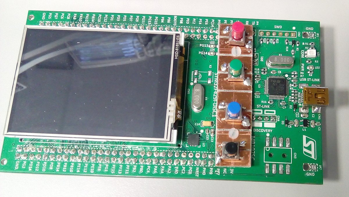
The PCB for mounting the push buttons is constructed from a piece of PCB material measuring 56mm x 13mm. The 2 mounting holes are drilled through using the DISCO board (or Vero Board) as a guide. The switch board can be mounted on the DISCO board using M2 nylon screws. I placed 2 x M3 nylon washers (on each screw) between the switch board and the DISCO board to provide enough spacing for it to not bind against the DISCO board itself. Leave this PCB board blank for now.
Raising The Display
In order for the tactile switches to protrude through the front panel by approximately 1mm, the LCD display must be re-mounted further away from the DISCO board. This is a horrible procedure that requires sawing through the existing foam 'mirror' pads that hold the LCD in place. From experience I can say that the best approach is to use a long razor knife or a Stanley knife blade and use a sawing action to cut through the foam pads. Do not be tempted to lever the display away from the board as it is quite thin and delicate. Also be aware of the flexi cable when sawing - you dont want to cut it.
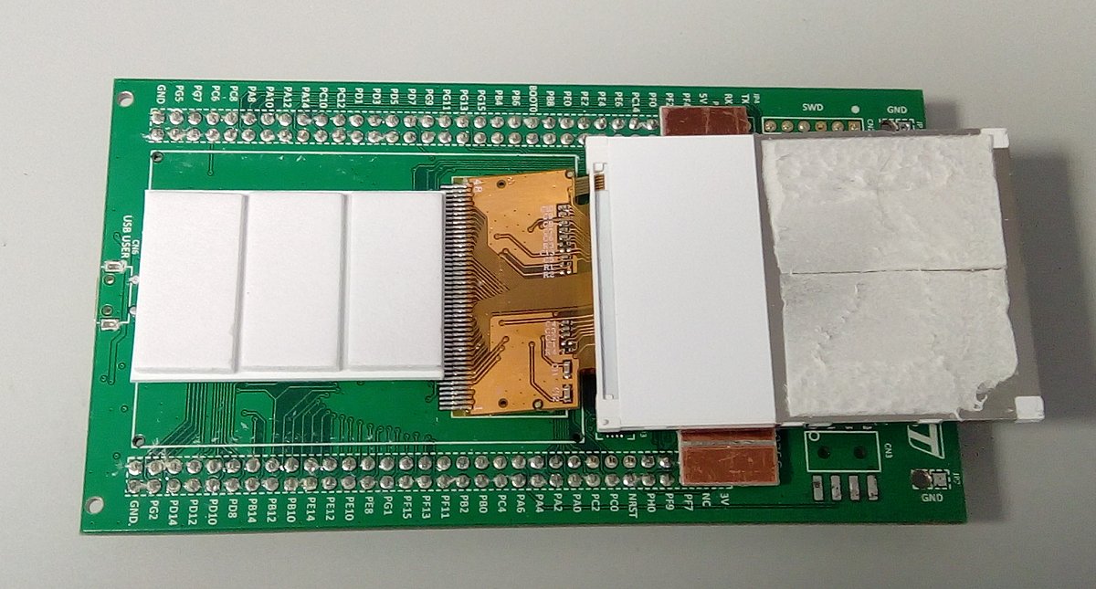
Once the display is free and hanging on its flexi cable, remove any remains of the old sticky pads and build a spacer as follows: Place new foam pads (~2mm thick) onto the board. On top of those, place some 2mm thick plastic. Finally add a 2nd layer of pads on top of the plastic. In total, the new space behind the LCD display will be 6mm.
When re-sticking the LCD, I would recommend not peeling the adhesive protection from any part of the new pads that would come into contact with the white plastic film on the back of the display - this is thin and delicate. It will be more than sufficient for the pads to be stuck to the metal part of the display. When you're ready, peel the pads and apply the display, taking care to keep it aligned with the edges of the DISCO board. You might even choose to NOT stick the display back at all and just rely on a friction fit between the foam spacer you have just constructed and the perspex window; this will allow the display position to be tweaked after assembly so you can get it just right.
Cutting The Front Panel
Note that this procedure discribes how I would do this 2nd time around - I found it very hard to get the display aperture and holes for the mode buttons in exactly the right place on the front panel...
It is now time to drill the DISCO mounting screws on the front panel. I placed the DISCO board centrally in both the X and Y directions against the front panel and marked where the 4 DISCO mounting screws should be drilled. The button board must be removed (or have no buttons) in order to do this. Fit the mounting screws and be sure that these are nice and true - 20mm long M2 nylon screws are quite flexy so I'd recommend fitting 10mm M2 metal pillars to the front panel and put short nylon screws through the DISCO board into the pillars.
Once the DISCO board is mounted SECURELY you can then go ahead and cut the display aperture and button holes. The visible part of the LCD display will need an aperture of 53mm x 40mm - this includes a 2mm border all the way round. The display aperture can be fettled with a file until it lines up nicely with the display - run the SDR software on the DISCO to check where the white perimeter line is.
The button holes should be drilled in a neat line. I spaced my buttons 0.6" apart and set symmetrically about the 2 screws mounting the button PCB (which are 1.3" apart). You'll be able to adjust where the switches are soldered on the PCB later in order to eliminate any mechanical alignment errors and binding.
Once the button holes are drilled, marks can be made onto the button PCB underneath so that the position of the 7 saw cuts can be decided. 1 saw cut goes under the centre of each switch and one between each pair of switches. Once these are done, the switches can be tacked in place by 1 LEAD ONLY to allow the mechanical fit to be adjusted. Keep adjusting the switch positions until all 4 align correctly with the holes in the front panel. (This took me ages - if you can recommend a better way of making this alignment please let me know!!). When you are SURE, solder the switches securely in place.
Perspex Display Window
The display window can now be made to fit the hole. Measure the aperture that you have made and cut a piece of 4mm perspex exactly 5mm larger (all round) than this aperture. The outer dimensions of this window must be accurate as we will use a router to mill a step along all 4 sides and this outer edge will be used to guide the router.
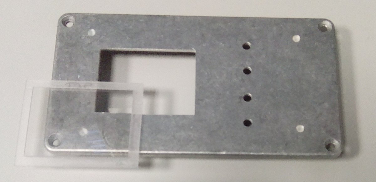
I mounted my router in a bench vice facing upwards. I used a 12mm bit (don't use a very narrow bit as it is more likely to bite into the perspex). Set the router guide to give something short of a 5mm wide cut and set the depth of cut to 2mm (half the thickness of the perspex sheet). I had to add a strip of wood to my router guide so that there was no 'gap' near the bit as this would make it impossible to slide the small window past the bit without it dropping into the gap (which would be bad). Ultimately the goal is to gently buzz the window past the router on all 4 edges and adjust the router guide very slightly until the window fits perfectly into the hole you have cut in the front panel. (REMEMBER to approach the bit from the correct direction otherwise the router will snatch the window and butcher it.)
Once the window is done it should sit snugly in the front panel and the LCD panel should press gently up against it. Adjust the DISCO mounting screw height as required.
Wiring Up Part 1 - The DISCO Board
As the mode buttons are captive to the DISCO board these can be wired up directly.
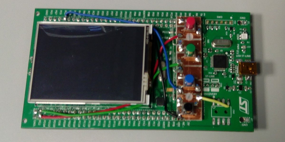
Wiring Up Part 2 - The Box
The power input socket, on-off switch (built into the 10k LOG volume pot) and voltage regulators can be built onto the rear panel of the box to provide good heatsinking. I have elected to go down from 12V to 8V with a LM7808 regulator to give a ripple-free supply for the audio amplifier and to lower the voltage applied to the radio board to reduce heating. (This is in place of the 27R dropper resistor on my original radio.) The 8V regulator then feeds into the LM7805 regulator that will feed the DISCO board.
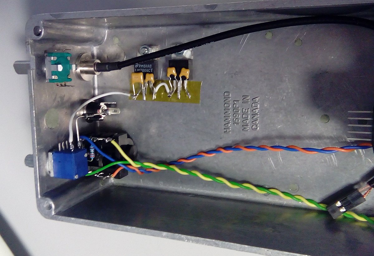
The antenna connection is a simple piece of coax.
The plan is for all connections from the box itself to attach to the front panel assembly via 0.1" headers.
Wiring Up Part 3 - The Interconnect Board
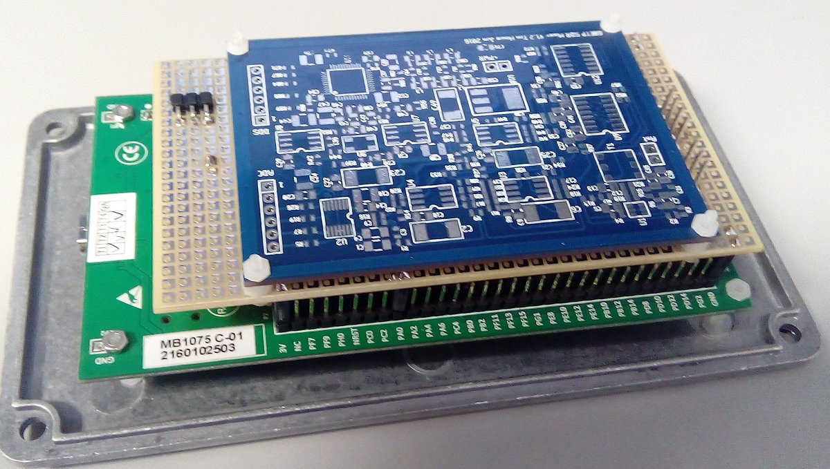
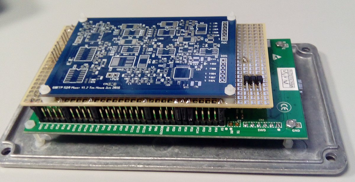
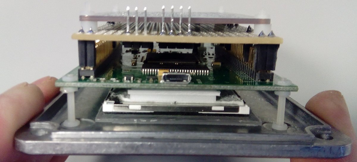
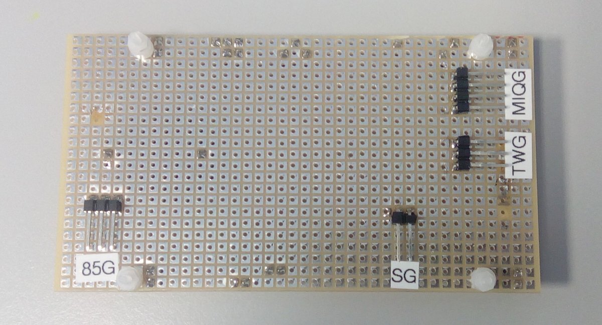
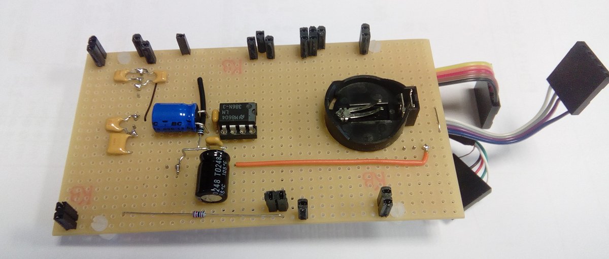
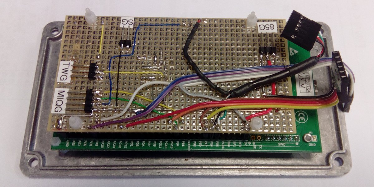
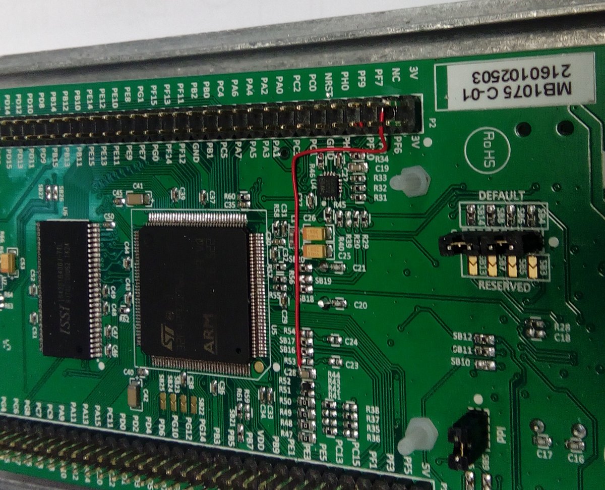
Besides the Vbat connection to the DISCO bord which has no pin, I propose that all connections to the DISCO will be made via an intermediate board. I am using 0.1" patch board with individual copper squares. (You could use a piece of Vero Board with copper strips at a push, but there would need to be more track cutting.) This board will pick up all the necessary connections from the DISCO via a bunch of individual 0.1" header sockets (made by cutting bits from a TBC female header strip.) This board will plug onto the DISCO and can be easily removed.
The interconnect board will carry the Lithium coin-cell holder for Vbat, the audio amplifier circuit and will provide a means to attach the radio board. It will also carry the various headers that will go to the side-panel controls, the voltage regulators and the loudspeaker.
Audio Amplifier
At present I am planning to build an LM386 amplifier directly onto the interconnect board. I have toyed with alternative amplifier ICs such as the ones that provide a Bridge Tied Load (BTL) speaker drive but there are complications when one tries to connect headphones. Some BTL ICs provide additional switching for this purpose but I need to stop to do some breadboarding...
More to come....
Other Pictures
Last updated: 17.02.2021