Tim's Multiplex FOX RC Conversion
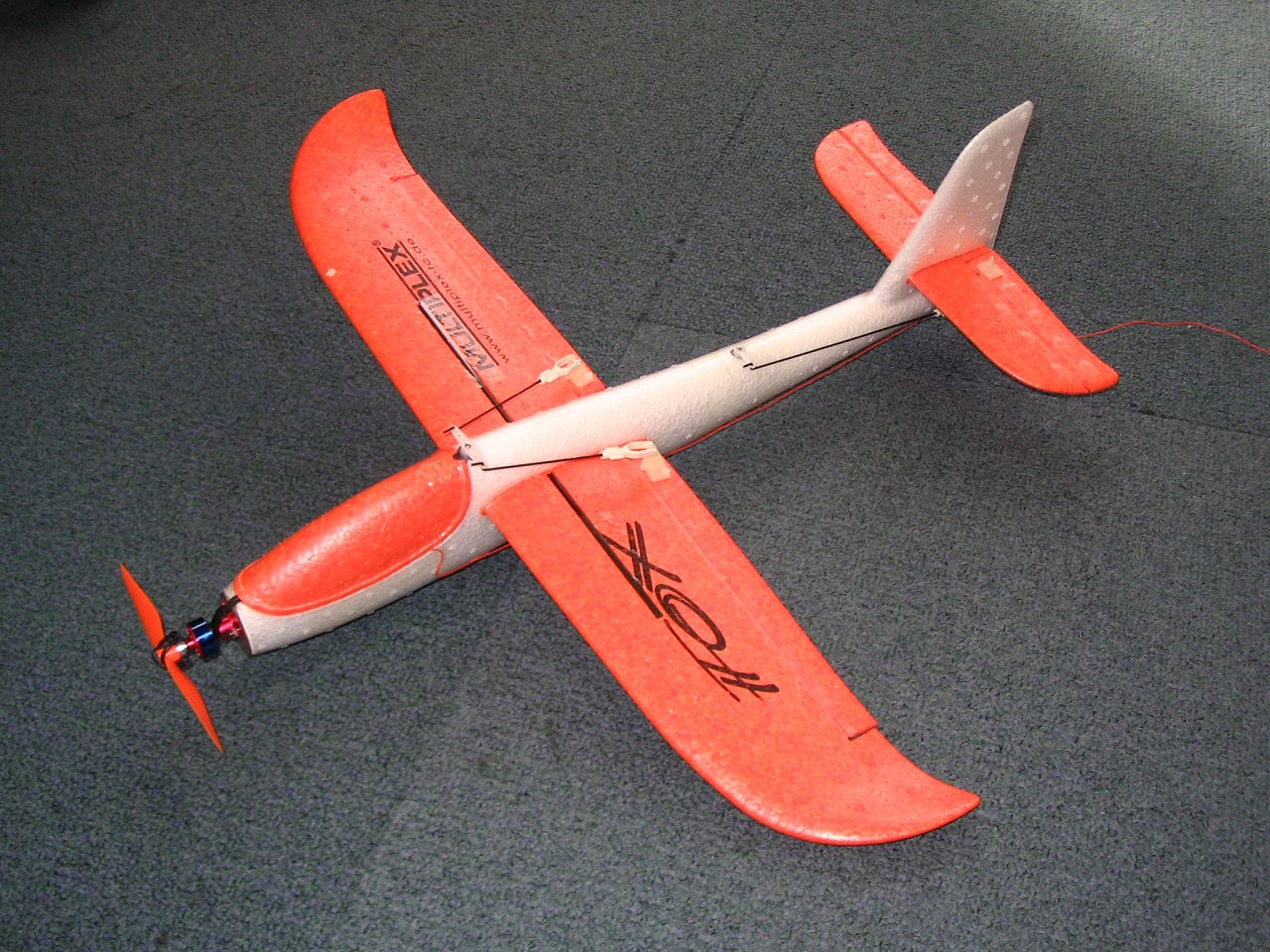
Some time in the late summer of 2009 I caught wind of a craze where people were modifying Multiplex Fox gliders (a cheap, injection-moulded foam chuck-glider) for RC. Fuelled by my friend Phil's enthusiasm to have a go, along with numerous youtube videos of people's efforts, the project began.
At the time, the glider kit cost about £8. It comprises a fulelage (with integral tail fin) and a wing and tailplane that slot in. The fuselage itself has a nose/cabin moulding that when puled off reveals a large ball-bearing nose weight.
Motor, Battery, Speed-Controller, Rx and Prop
The motor is a Turnigy 1811-2000 (Kv=2000rpm/V) that weighs 11g and should be good for 14500rpm with a 2-cell LiPo. The batteries I use are Zippy Flightmax 350mAh, 2S, 20CI. These weigh 21g and measure 40x20x15mm. The speed controller is a (TBC). The Rx is a Corona RP8D1 synthesised 35MHz micro-receiver that does not require Xtals and weighs (TBC)g. Although they tend to break quite easily, the propellors I prefer are the orange GWS EP 4540 (114x102mm) ones, as they are very light and efficient.
Construction Details
My 'personal' design methodology is to always go for a clean and simple solution. This usually involves looking at something for a while and pondering options in my mind. I could have followed other designs from the internet but this is just not the way I work! In the end, my solution was as follows:
The space under the canopy was hollowed out to house the Rx and the speed controller. The aileron and elevator servos were going to be mounted as described below to allow straight control linkages. Finally, the battery was going to be mounted in the underbelly of the fuselage and positioned to set the final C of G.
The aileron servo is mounted in a hole cut into the top of the fulelage just behind the canopy where it can drive pushrods directly out to the ailerons. The canopy moulding then helps to hold the servo in place. The aileron servo wire is already in the canopy space close to the Rx.
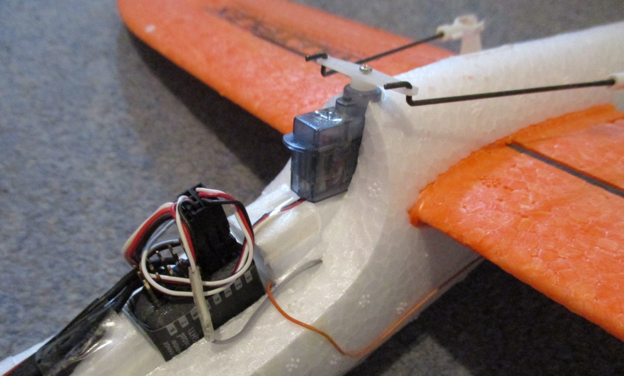
The elevator servo was mounted inside the fuselage mid way between the wing and tailplane so that it can again drive a straight pushrod to the elevator. This involved first cutting a trapizoidal-section out of the fuselage to act as a sort of 'lid' to hold the servo in pace. Then the hole for the servo was tunnelled and a hole made in the lid to allow the the servo output shaft to pass through. The wiring was more difficult for this one: A tunnel was drilled inside the fulelage using a 4mm section of brass telescopic aerial as a hole cutter. One tunnel was drilled from the wing aperture to the elevator servo and another from the nose cavity to the wing aperture. (This was a bit of a 'meeting in the middle' problem, a bit like the Channel Tunnel!) Once this tunnel was drilled, the servo wires had to be extended so that they could be threaded all the way to the nose cavity, at which point the servo plug could be re fitted. Finally the lid can be taped down on top of the servo to hold it in place.
The Rx was mounted vertically as shown below, giving easy access to the connectors. This required quite a bit of tunnelling of the canopy to make space. The speed controller was mounted in a slot tunnelled out alongside the Rx also as shown:
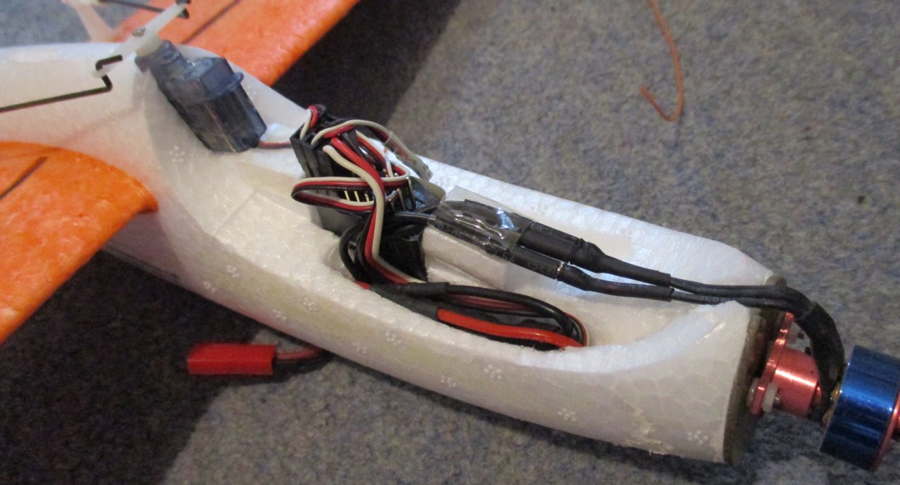
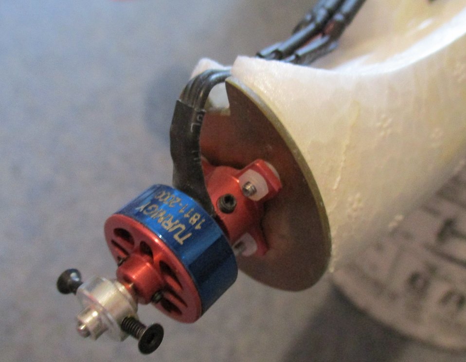
The motor mount involved cutting the tip off the fuselage with a bread knife. You can allow for a little right and down-thrust at this point, although further adjustment to these angles can be made later by placing washers under the 3 legs of the motor. The mount itself was an egg-shape disk cut out of 1.6mm thick fibreglass PCB material. This was drilled to accept 3 x M2 screws which were then made captive with a blob of solder on each screw head. (Nothing worse than blind screw-heads turning!) A small rectangular cut-out was made at the top of the engine mount to allow the motor wires to enter just under the cabin moulding. Finally, the mount was glued to the fuselage with RTV (like silicone bathroom sealant but much stronger); this remains flexible and is therefore less likely to crack away from the foam. Nylon nuts were considered amply strong to attach the motor and it is hoped these will protect the captive screws.
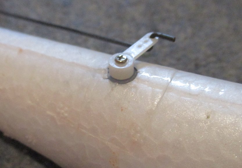
The aileron and elevator surfaces were each cut out with a scalpel, making a vertical cut. Once the pieces were loose, both the wing edge and the control flap edge were bevelled to allow a nice hinging action: To do the bevel, simply hold a steel ruler along the desired edge but back by a few mm, then saw off the unwanted foam with a scalpel. This will allow the control flaps to butt-up close to the wing and still hinge by +-45 degrees. Once the flaps have been cut, a U-link must be made to join the 2 halves of the elevator together so they act as one. For this I used some of the same 1mm control-rod as for the servo control linkages.
The hinges wre formed by applying 1-inch medical adhesive tape on each side of the hinge. This medical tape is like a soft and permeable vinyl and is much more pliable and sticky than sellotape. After 7 years, the glue still seems to be strong and stable. The only slight problem I had was keeping the 2 layers of tape pinched together in the crease of the hinge. In the end I resorted to hand stitching the top through to the bottom along the hinge line and now the hinge fulcrums are tight and straight.
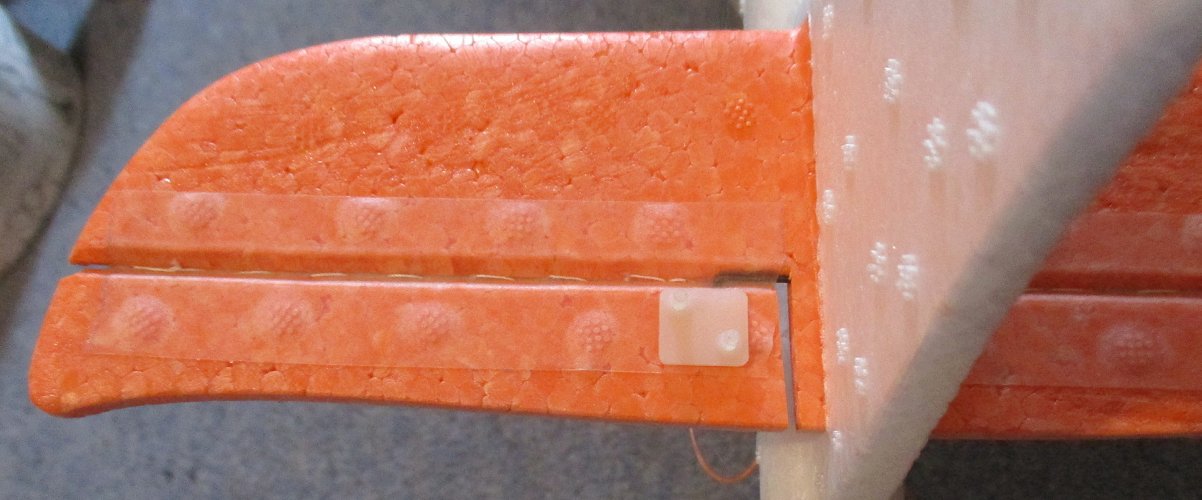
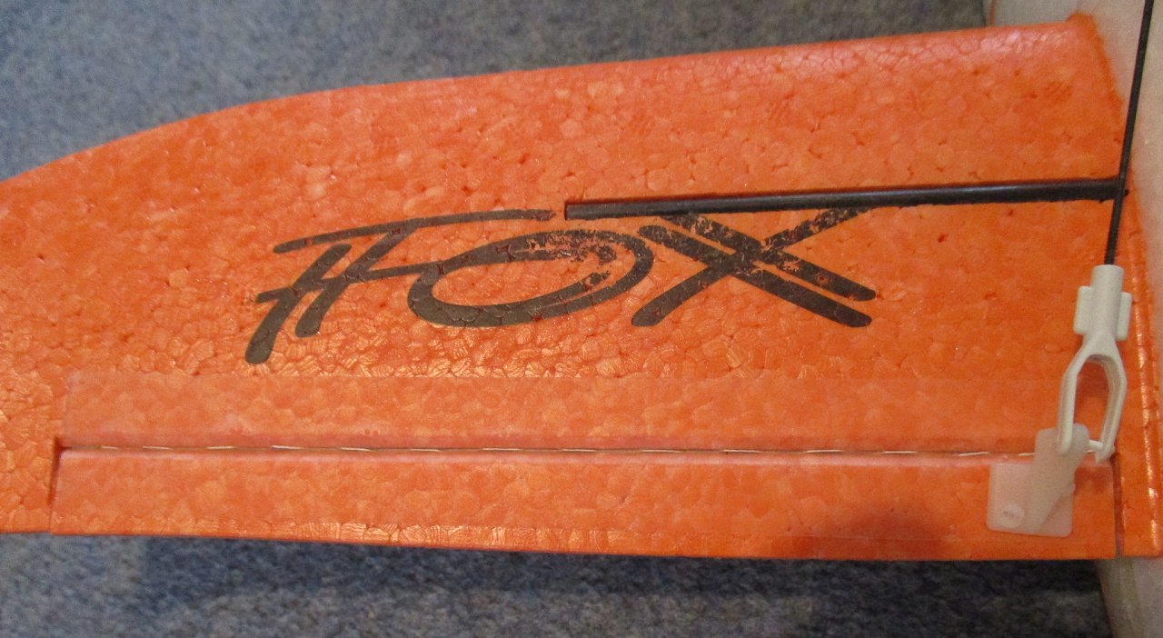
The aileron picture above also shows a carbon-tube spar that I have added to brace the wing. As this plane flies quite fast, there is a tendancy to pull turns much tighter than the foam wing was ever intended to handle. I had a spare 4mm diameter carbon tube lying around so added it to the top of the wing so that the load from turning is now transferred to the fuselage where the wing passes through. In order to fit this tube, I made a small hot-wire cutter to cut a U-section slot into the foam. This was a total success and the tube just dropped into the recess. (Note thats its a bit harder than this really, since the wing root is thicker than the rest of the wing. I cant remember whether I drilled laterrally under the wing root or cut a piece out and glued it back on top of the wing spar. Either way, this piece of foam needs to be there to pass the spar load to the fuselage.) Finally I secured the rod in the wing with cyano but one could equally use more medical tape.
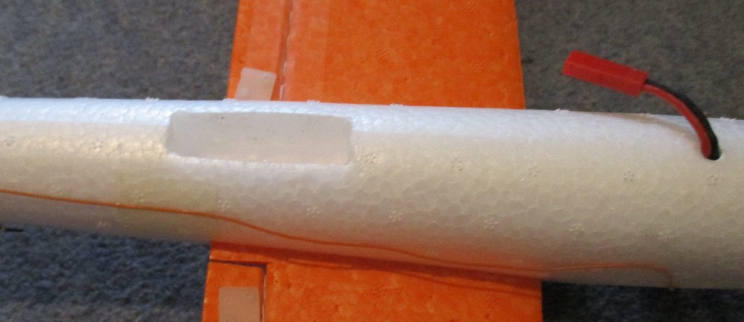
Last of all, a slot needs to be cut into the underbelly to hold the battery. I suggest attaching the battery with tape or bands for a few flights until you are happy with the C of G and then make the cut. My battery still stays in place by friction but one may need to resort to a rubber band eventually when things 'get a bit saggy'.
Flying
The Fox is a blast to fly. There is actually too much power available with the specified motor and things can get unstable / uncontrollable at full throttle. The plane flies best at 25-50% throttle and still potters around at quite a lick.
Video 1: Fox flights 1 and 2 filmed at lunchtime by Phil Duff. Quality is not great as this was deinterlaced and transcoded to h.264 from an MPEG2 file. I need to dig out the original DV tape...
Last updated: 2.6.2016