Portable Build of the Mk2 SDR HF Receiver
This page provides some details on boxing the Mk2 receiver in a fairly portable package.
Choosing A Box
I decided to use a plastic Hammond RP1175C box. The reason being that this has a transparent lid and my hope was that the STM32 DISCO board could be mounted directly behind the lid without the need to make a transparent window for the LCD. My plan was also to mount the DISCO board very close behind the lid so that the LCD display would not have to be removed from the DISCO at all, since this is a difficult process that can lead to damage.
DISCO Board Preparation
We will see later that I have mounted the DISCO board using 4 5mm-tall M2 pillars, with an additional 1mm (2 M2 washers) to allow room for the 4 push buttons. In order to mount the DISCO board this close to the panel, the following modifications must be made:
Drilling the DISCO Board Mounting Holes
Sadly, the STM32F429I Discovery board has no mounting holes. I have checked the Gerber files and it is safe to drill 4 M2 mounting holes in the following places; 0.2" down and 0.1" to the side of the CORNER pins of P1 and P2. Place a piece of 0.1" prototype board over P1 or P2 to provide a drilling guide. Begin with 1mm pilot holes then open these out to 2mm.
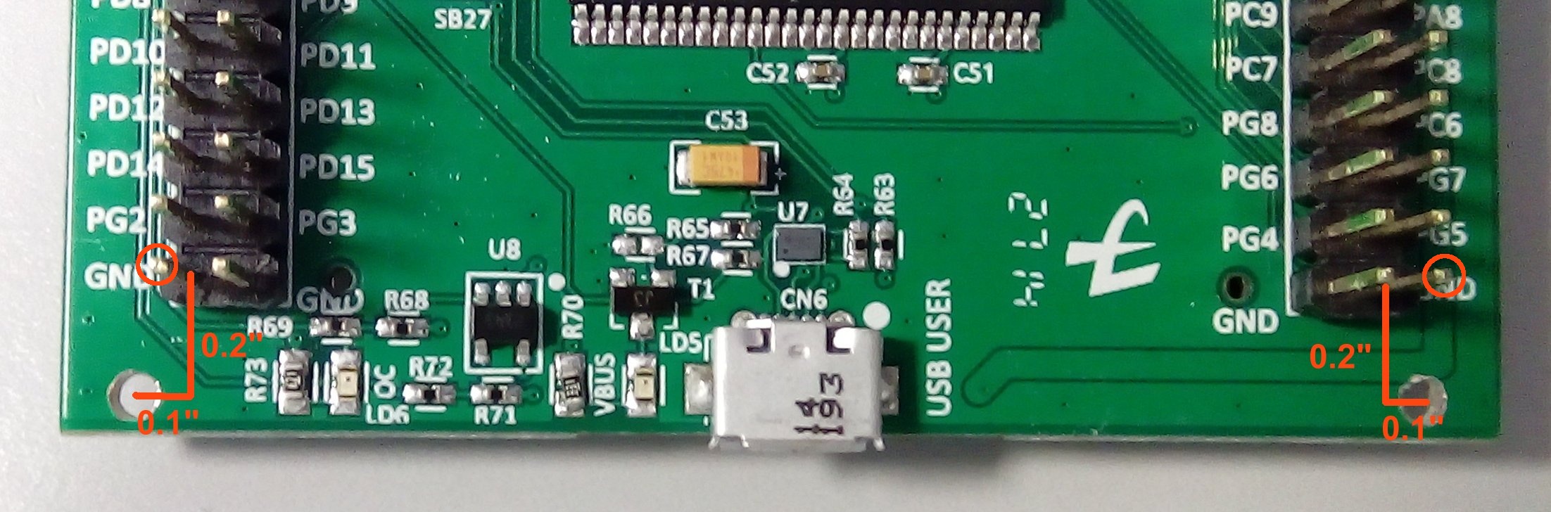
At the other end of the board the holes are 0.1" out from the end pins of JP1 and JP2 as shown. Again use 0.1" proto board located over JP1 and JP2 as a drilling guide:
DISCO Modification for External Vbat Supply
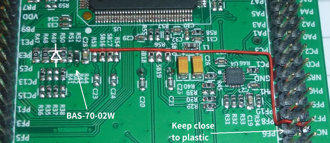
3V is provided by the radio board to power the CMOS RAM within the STM32F429I MCU. Unfortunately, ST have hard-wired Vbat to Vdd on the PCB, so it is necessary to add a shottky diode between Vdd and the Vbat pin. The following picture shows how R52 can be replaced with a BAS-70-02W diode. Once this is done, a wire can be run from C28 to the NC pin on P2 pin 4, which is where the battery supply comes in from the radio PCB:
Box Lid Drilling
I have made a drilling stencil to help locate where the 4 x M2 DISCO mounting holes and 4 button holes need to be drilled. The plastic lid is very easily scratched, so during machining I had a plastic protection layer taped to the lid; this was cut from a plastic A4 wallet.
Button Mounting
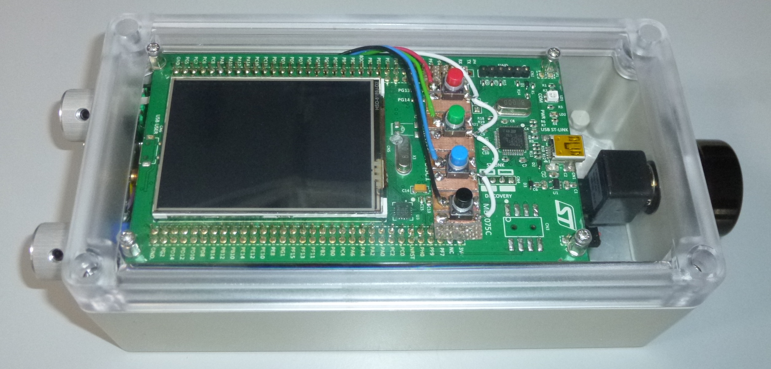
I like to mount the 4 push buttons in a row to the right of the LCD display in order to make use of the otherwise redundant 'real estate' between the LCD and the ST-LINK USB connector. With the DISCO board mounted very close behind the box lid, this presents quite a challenge, since the height available for push buttons is extremely limited.
I looked at various low-profile tactile buttons but failed to find any with a suitably long actuator to pass through the front panel (which is > 2mm thick). In the end I went back to using Diptronics DTSM-644K SMD switches that can be fitted with coloured plastic tops. In order to accommodate these between the front panel and the DISCO board, the (hand-made) button carrier board needed to be made out of very thin (0.8mm) PCB material. I also needed to increase the distance between the DISCO board and the panel to 6mm by adding 1mm of washers to each pillar.
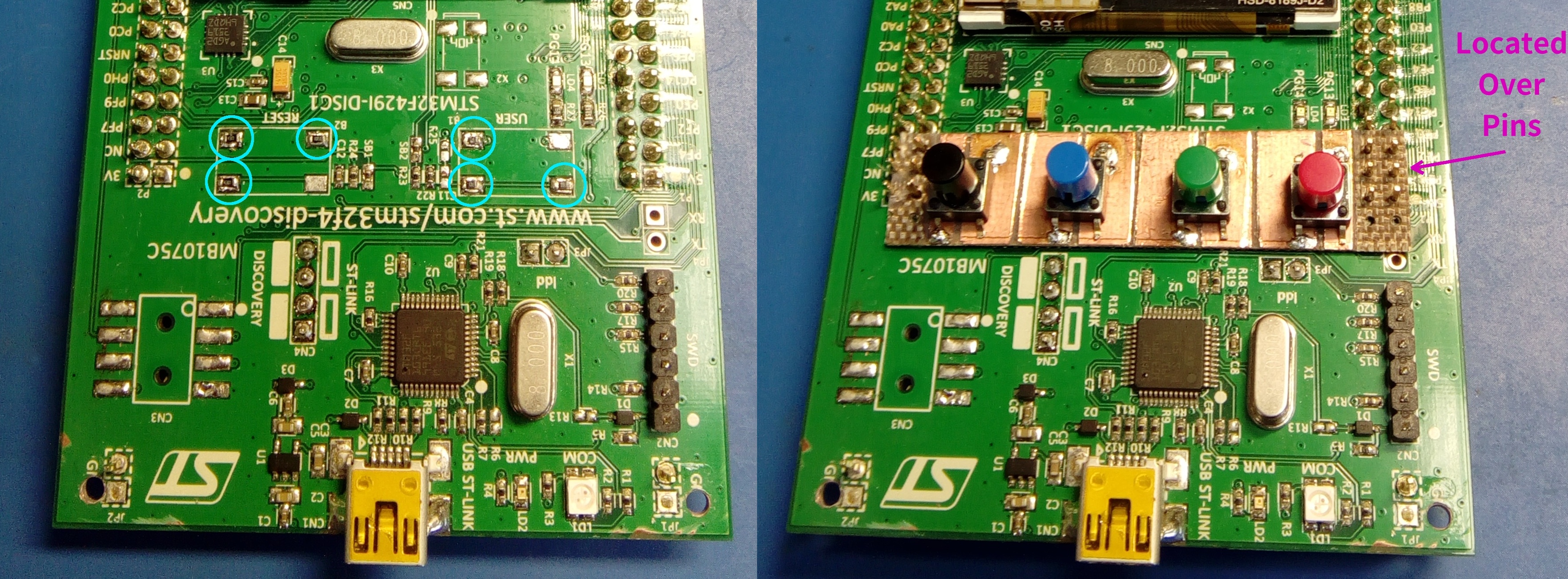
Since the button board is so thin, I added some 0603 resistors to the pads where the USER and RESET buttons were located (see blue circles) in order to provide a more level surface for the button board to lean against. Using a piece of 0.1" prototype board as a drilling guide, drill 12 1mm holes in the button board so that it fits over 6 pins on P1 and 6 pins on P2.
Next, mount the M2 pillars on the front panel so that the DISCO board can be slipped on and off easily. This way, the DISCO and button board position is quite stable but can be repeatedly removed while lining up the buttons. Now you can go ahead and drill the 4 holes in the front panel. Button spacing is 0.5" and the drill centres for the front panel holes are included in the drilling stencil. This is a chance to shift the horizontal position of the drilling stencil (or re-make the button board if things are not lining up well).
Once the panel has been drilled, mark the button board with a pen (through the front panel) where the button centres will be. Remove the button board again. Use a hack saw to make 7 shallow cuts so that the copper is divided into 8 separate lands.
Next, solder the 4 buttons by 1 leg only and test the button placement by placing the DISCO board back on the pillars. Adjust the button placement until the buttons are in exactly the correct place and do not bind in the front panel holes. When you are completely sure, solder the opposite pin of each button so that they are secure. The next photo shows the buttons protruding through the panel and the wiring made off to the radio PCB. (Note you can just make out the 2 x M2 washers on the DISCO side of the 5mm pillars.)
Preparation of Rear Box Section
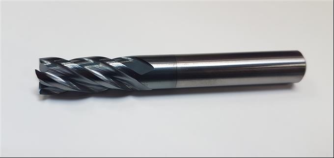
The Hammond box has a number of moulded mounting pillars on the inside. In order to help dissipate heat from the voltage regulators I have made an aluminium plate that sits in the rear of the box. For this to fit snugly on the rear face it was necessary to remove the mounting pillars. There are various ways to do this. If you are lucky enough to have access to a flute mill (like this) and a pillar drill then this will be easy. If not, a normal 10-12mm drill can be used to remove the bulk of the pillars. A pillar drill is still useful but this can be done by hand. Finally, a wood chisel may be used to shave down the remaining stumps so the box interior is flat.
An aluminium plate can then be made to fit. I decided to fix this plate into the box with contact adhesive, thinking that this would keep it in place while I was drilling the many holes in the rear panel. However, as the plate was made of soft aluminium, every hole drilled created burrs, and the combined force of the many burrs prized the plate away from the rear of the box. In the end, the plate had to be removed and all of the holes de-burred before it could be refitted.
Loudspeaker Grille and Mounting
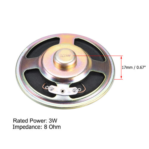
You will need quite a thin loudspeaker. The one I used was 77mm diameter (3") and only 17mm deep (like this except that mine was 4Ω). I would have liked to have had space for a better quality speaker because the audio from this radio is very good. Do some experiments with the radio assembly in place to make sure your speaker will fit. Once the location is decided you can drill the speaker holes. For this, I attach a piece of metal with triangular / hexagonal perforations to the rear of the box with a glue-gun and use this as a drilling guide. The first phase is to drill 2mm pilot holes (~170 of them). After these are done, the drilling guide can be removed from the rear of the box and the holes opened up to 3mm. You will probably then have a lot of de-burring to do. Finally, to fix the speaker to the rear plate I used 4 blobs from a glue gun.
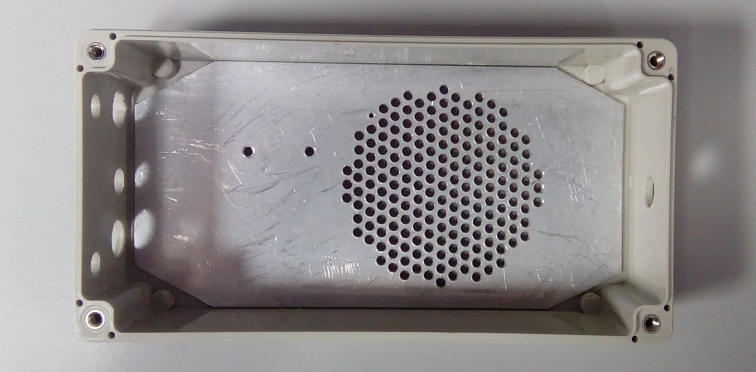
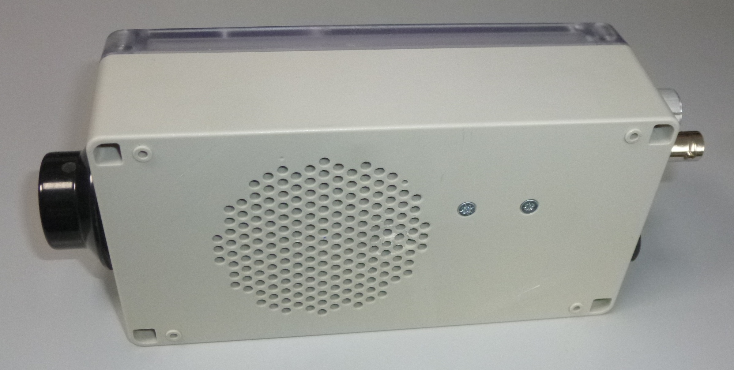
Rear view of the radio showing the speaker grille:
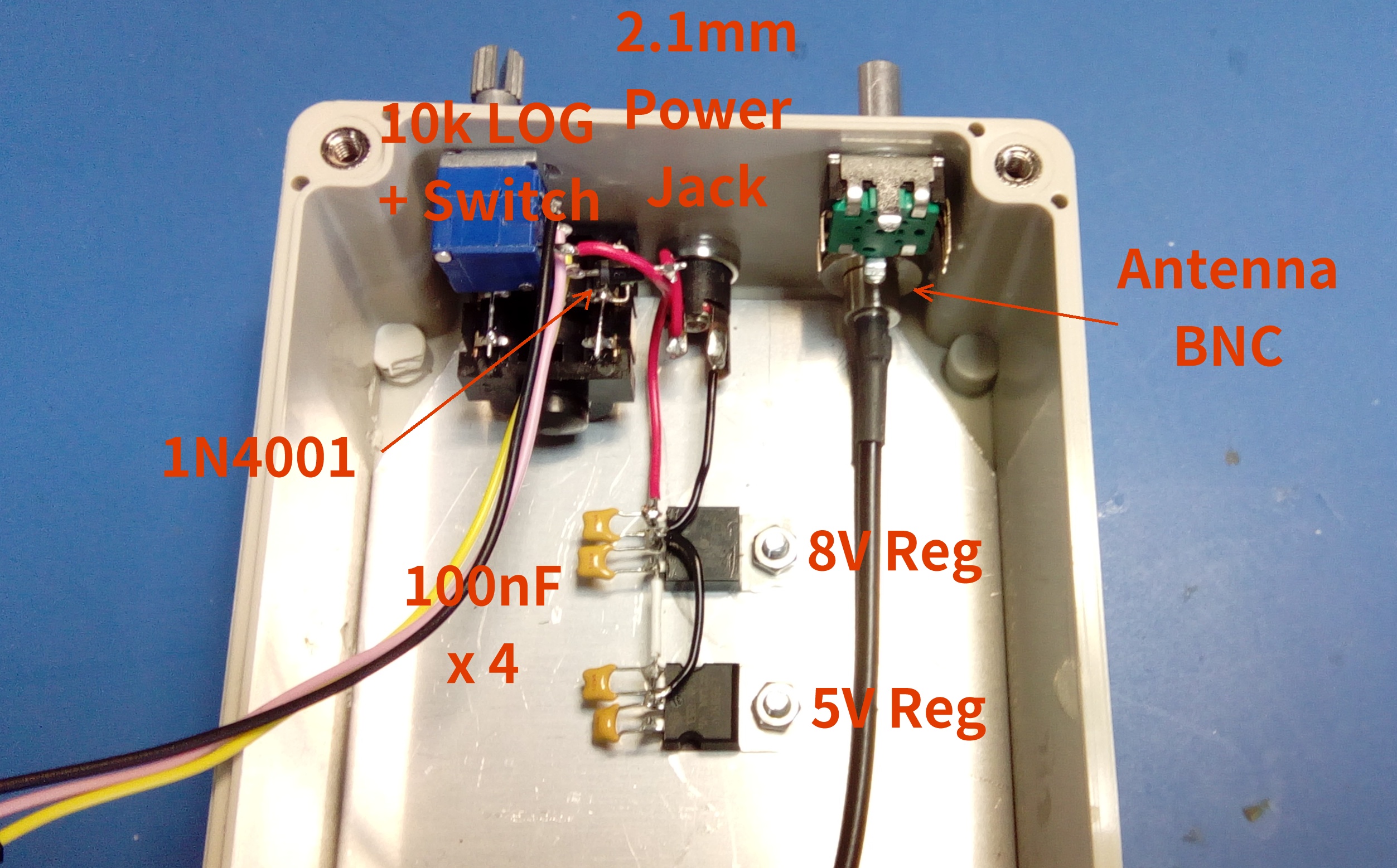
On/Off, Volume, Menu, Headphone Jack, Power Jack and Antenna Jack
Holes can be drilled to accept the controls and I/O ports on the left hand end of the box. Due to the switching and attenuation arrangement I have used for the headphone jack this needs to have 3 switches. It is possible to get these in 3.5mm size but 6.25mm ones are more common. The power input connector is a 2.1mm centre-pin power jack. A 1N4001 diode runs from this jack to the on/off switch to give reverse polarity protection. The switched 12V input power goes to the 8V regulator, then the 8V from that goes to the 5V regulator.
Antenna Connection, Preselector Filter RF Connection and 6dB Pad
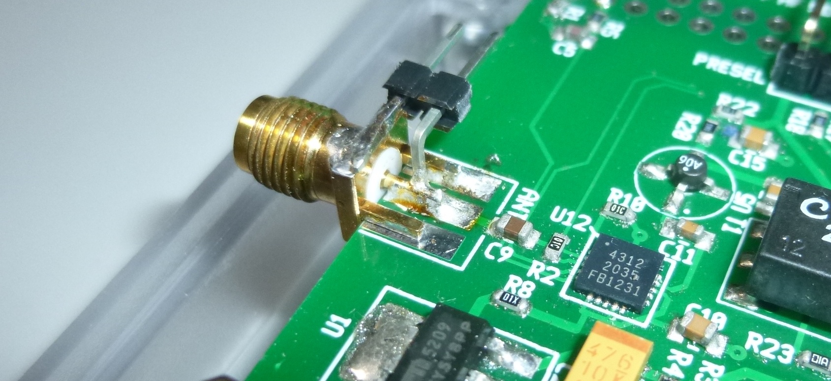
The SMA connector on the radio PCB sticks out way too far to leave room for an SMA plug. I have therefore decided to mount a 2-pin header onto the SMA at 90 degrees so that a Harwin M20 connector can make the antenna connection to the radio board:
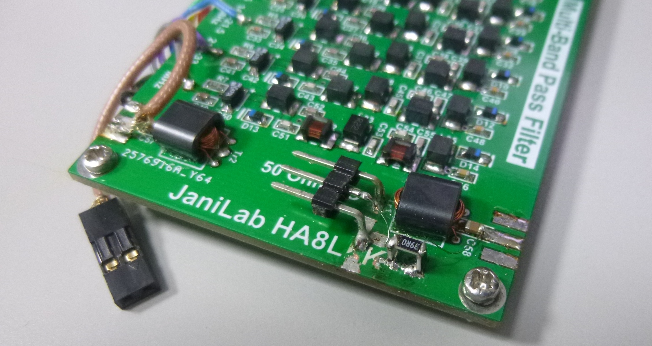
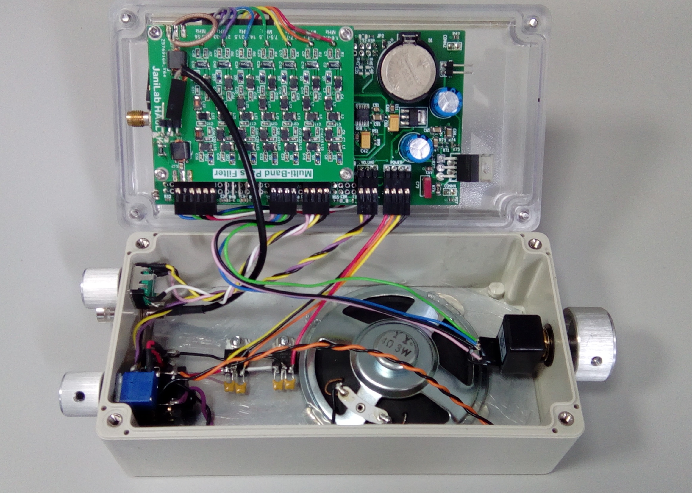
Sililarly, the SMA connectors fitted to the HA8LFK preselector board take up way too much space and have been removed. The output side of the filter board has a short coaxial cable run to the radio board. The input side of the filter has a 6dB pad and a 3-pin header, 2 pins of which are ground and provide mechanical support. The 6dB pad is a pi-network composed of 2 1206 150R resistors and 1 1206 39R resistor, mounted tomb-stone style. Thin wire is used to connect to the pad so that any mechanical flexing of the 3-pin header does not cause the pad to break. (The pad is there so that antennas that present a poor impedance do not spoil the response of the preselector filters. There is a 6dB Noise-Figure hit but this is not important on HF.)
The following picture shows the box connections made off to 0.1" headers (Harwin M20 series). It also shows the tuning encoder mounted on the right-hand end of the box:
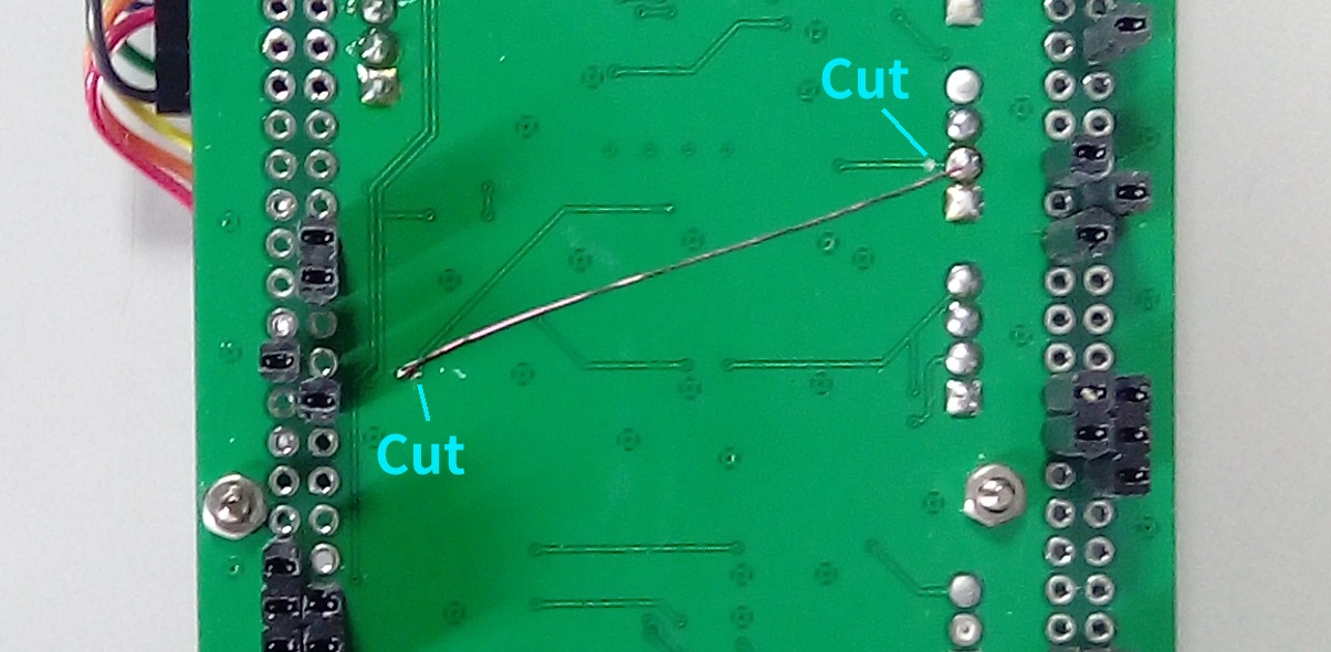
Tuning-Buzz Fix
There are a number of tracks on the radio PCB that have to cross from one side to the other to reach the required pins on the DISCO board. One such track is TUN_CH1. Like a moron, I had routed this track, carrying 5V logic signals from the tuning encoder, right underneath the relatively high-impedance IQ amplifiers. The following picture shows a cut-and-strap where this track can be bypassed with a wire running on the ground-plane side of the board. This completely solves the buzz that can be heard when the tuning knob is rotated:
The Finished Receiver
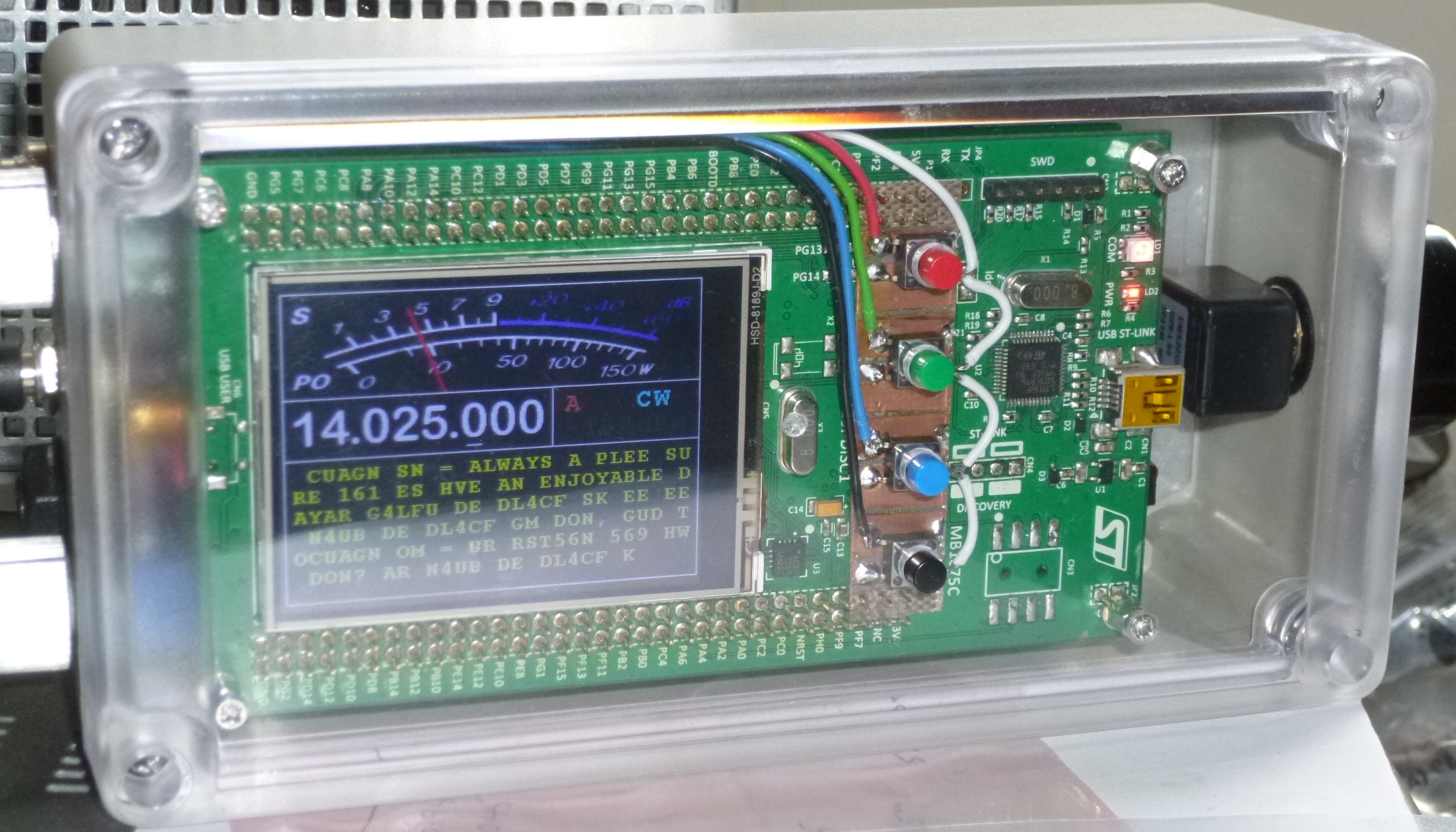
Finishing Touches
I had originally planned to mask off the area in front of the LCD then paint the inside of the box lid to hide the DISCO board. Instead, I think a better plan will be to cut a mask out of thin plastic or black paper and mount this between the DISCO board and the front panel. There is always the possibility of paint leaking under the masking tape and spoiling the edge of the LCD window, so I think this second option will be safer.
Last updated: 25.12.2022