G0ETP IAMBIC/Straight/Memory Keyer with Remote-Keying Capability
Since my trusty old TS450S does not have an internal IAMBIC keyer, I wrote code for an STM32 Nucleo board a few years ago to do IAMBIC keying, as well as sending text for beacon / CQ use. As part of making my own control system for remote radio operation, I added the ability for two of these keyers to be linked over a network connection to provide remote radio CW-keying with extremely low jitter and strong immunity to network delay.
A remote CW solution based on 2 of these keyer boards works out MUCH cheaper than using commercial boxes that achieve much the same thing. See Remote CW operation on a shoe-string for more information on how I operate a remote CW station for close to zero expense!
Keyer Schematic
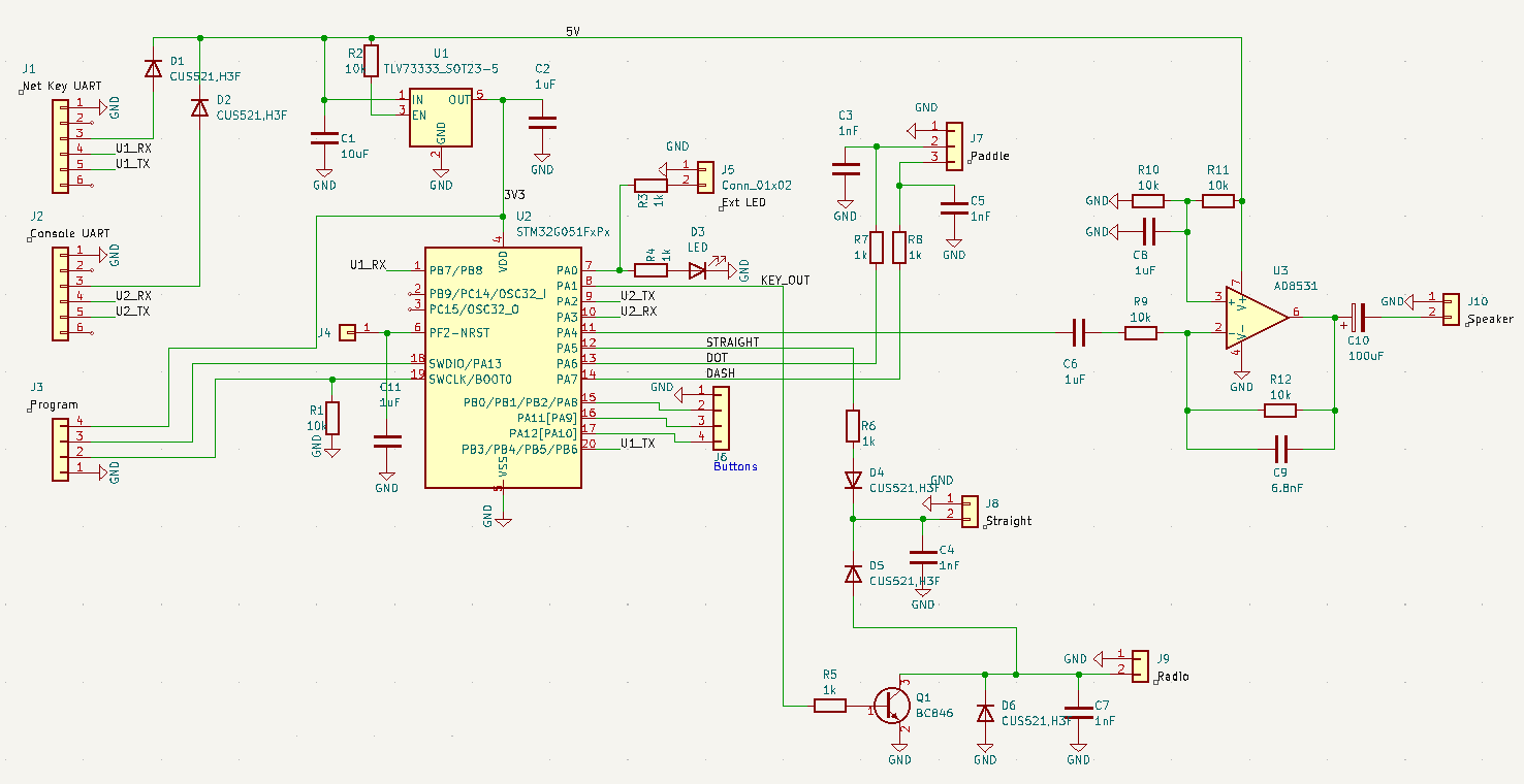
The keyer is based around an ARM Cortex M0+ processor in a TSSOP-20 package (STM32G051FxP6). 5V power for the board is provided via a USB-TTL serial adapter connected to either of the 2 6-pin serial port headers. To program the device, a 4-pin header is provided and you will need any STLINK programmer (V2 or greater), either an official ST one, the one built into an existing Nucleo board or one of the many low-cost clones available online.
Working back from the radio, we have an open-collector transistor Q1 to key the radio via J9. Since some radios have a relatively high idle voltage on their key pin, D4 stops this from damaging the CPU input. The straight key is able to key the radio even with the unit powered off which I find useful, for example for tuning my auto ATU. Diode D5 prevents CPU/transistor keying from activating the straight-key CPU input. The paddle key inputs on J7 require no special logic. The AD8531 low-impedance op-amp is used to drive a loudspeaker from the CPU DAC output. Side-tone is a 700Hz sine-wave with nice pulse shaping. Volume control is done in software.
Serial port connections to a host PC are made using 3V3 TTL232R cables from FTDI (which are £20 each). You can use cheaper, unbranded alternative 3V3 TTL cables, such as Prolific PL2303 USB-3.3V TTL cable (< £3 each but watch for Windows refusing to drive these devices), Silabs CP210x USB-3.3V TTL cable (Aliexpress £1.20, works in Win10) or CH341 USB-3.3V TTL cable (Aliexpress 80p!!, need to install Win driver). Note, all of these chip types work under Linux without additional drivers (of course they do...).
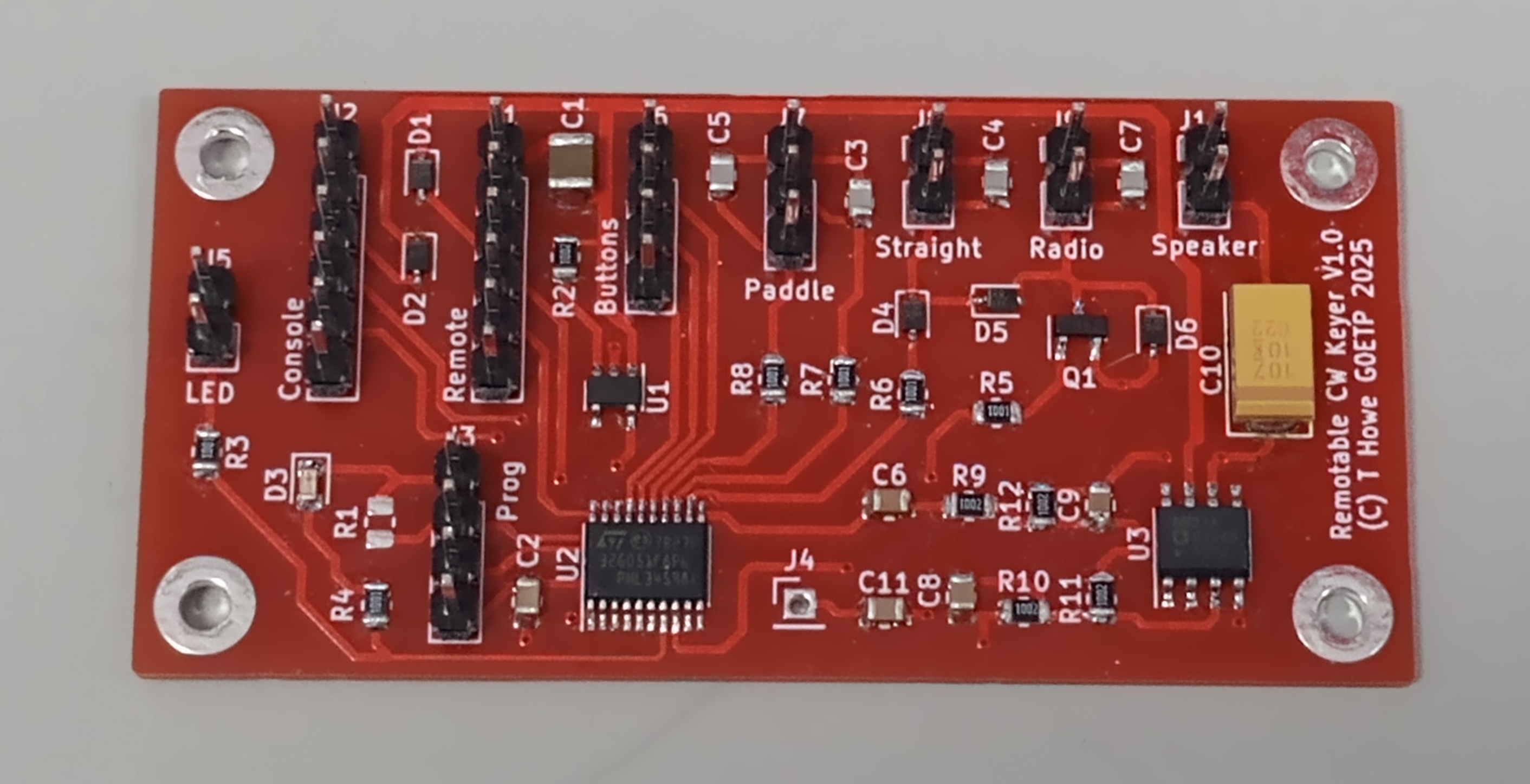
Keyer PCB
Keyer Operation
The keyer presents a human-friendly command-line interface via its Console serial port. The help screen looks is something like this:
CMD:?
Commands for G0ETP CW Keyer V1.30 on on STM32G051FxP (C) Tim Howe 2020-25:
Has 18 memories of length 100 chars. Buttons 1-3 will start keying memory 1-3
B[100-2000] Show/set network buffering delay
C[1000-5000] Show/set network key-up cutoff time
D Disable/stop memory keying
E
The radio may be keyed using a straight or iambic paddle at any time. Memory keying can be started using 3 hard-wired buttons or by issuing a command in the terminal window.
Remote Keying Data Stream (based on but not the same as CwCom protocol)
When network-keying output is enabled, the keyer will output a string of key-down (+ve) and key-up (-ve) timestamps in ms to the console which can be forwarded over a network to a remote instance of the keyer. On the PCB version of the keyer, there is a second serial port dedicated to outputting the remote keying data; this avoids having to share the command console serial port for both functions. With 2 ports, it is possible to have both the keyer command terminal session and a connection to the remote keyer active at the same time.
Besides receiving typed commands, the command console serial port is able to receive CwCom timestamp sequences at any time and will key the radio accordingly.
(Detail: The first value in a sequence is a key down plus the duration of the previous key up. If this key up duration was longer than the key-up cutoff time (typ 3s), a value of -0 is sent instead. -0 is recognised by the receiving keyer as an opportunity to re-start its network pre-buffer delay (typ 0.3s). This means that the remote keyer will reproduce your keying with a delay of (internet)+0.3s. The process of re-baselining the network pre-buffer delay after long gaps eliminates any timing creep that may result from Internet latency or clock rate differences between sending and receiving keyers.)
An example showing 'CQ CQ' at 21wpm:
-0 +165 -55 +55 -55 +165 -55 +55 -165 +165 -55 +165 -55 +55 -55 +165 -825 +165 -55 +55 -55 +165 -55 +55 -165 +165 -55 +165 -55 +55 -55 +165
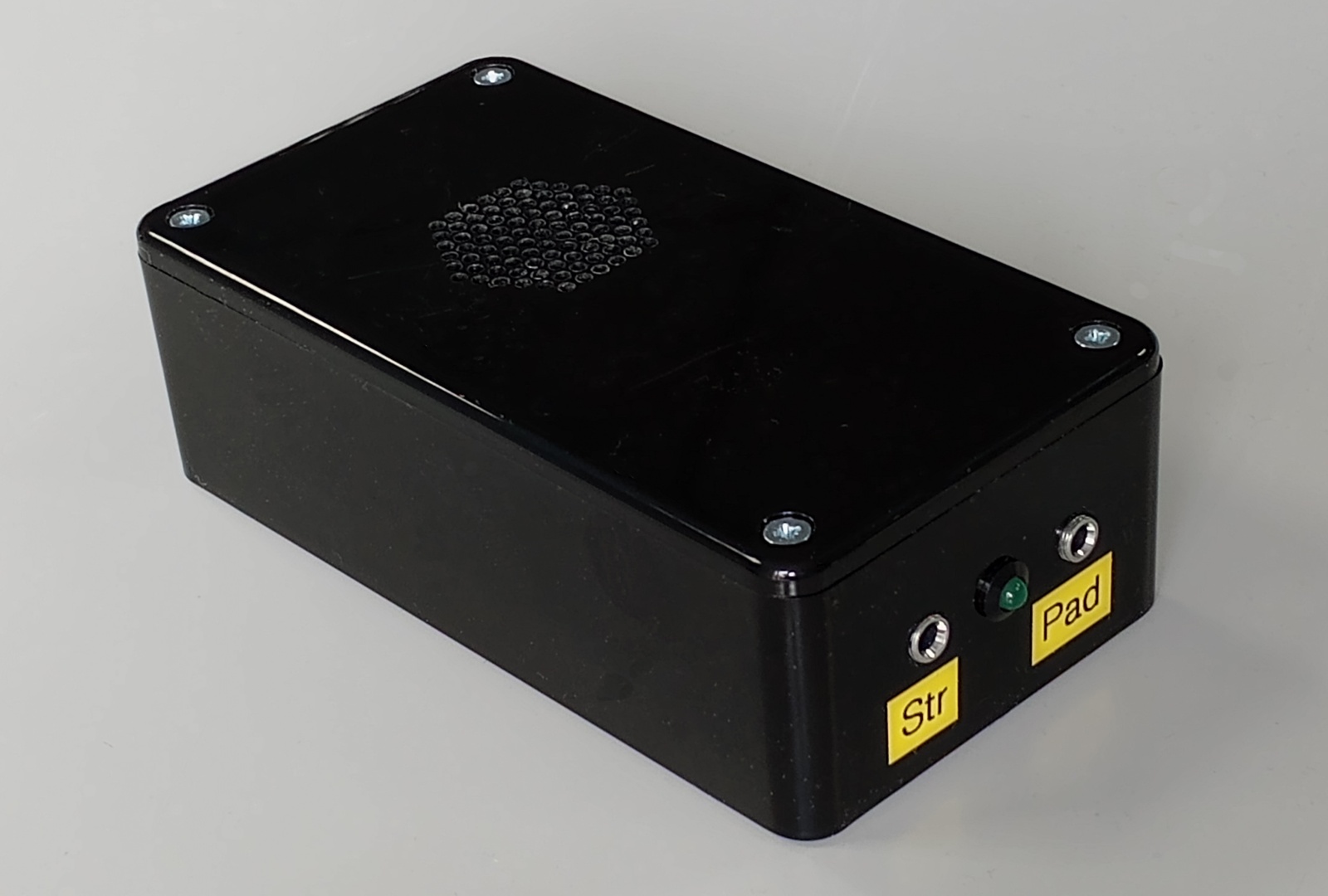
Keyer Enclosure
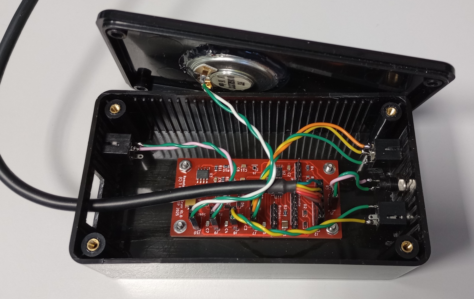
The keyer will easily fit into a 120 x 65 x 40mm plastic box. Jack sockets for straight and paddle keys are needed, along with a jack socket for a cable to the radio. There is also an LED on the front of the box to show when keying is active. A loudspeaker will be needed for the sidetone. I recommend a 16ohm speaker but an 8ohm speaker will work fine if that's all you have. As with other projects, I use a piece of perforated metal sheet as a drilling guide to make holes for a speaker grille. Prior to drilling, fix the metal sheet to the box lid with a glue gun. After drilling, remove the metal sheet then use the glue gun to attach the speaker.
For the USB serial cables, my original plan was to mount a pair of 6-way pin headers on veroboard just behind a rectangular hole in the box so the USB cables could be attached/removed without needing to unscrew the lid. For now though, I have simply passed the USB serial cables through the hole.